

Official Class 12 Physics Worksheets: Chapter 04 Moving Charges and Magnetism
Explore structured practice materials through the CBSE Class 12 Physics Moving Charges And Magnetism Boards Questions Worksheet. Tailored for Class 12 learners, utilizing these Physics worksheets ensures thorough preparation and strengthens problem-solving accuracy before final school evaluations.
Solved Practice Worksheets for Physics
Access the complete worksheet PDF for Class 12 Physics below. Regular practice with these targeted academic tasks builds familiarity with standard question patterns and helps secure higher marks in final school examinations.
Important Questions for NCERT Class 12 Physics Moving Charges And Magnetism
Question. An electron having mass m and kinetic energy E enter in uniform magnetic field B perpendicularly, then its frequency will be
(a) eE /qvB
(b) 2πm /eB
(c) eB /2πm
(d) 2m /eBE
Answer : C
Question. Two parallel wires in free space are 10 cm apart and each carries a current of 10 A in the same direction. The force exerted by one wire on the other, per metre length is
(a) 2 × 10⁻⁴ N, repulsive
(b) 2 × 10⁻⁷N, repulsive
(c) 2 × 10⁻⁴ N, attractive
(d) 2 × 10⁻⁷N, attractive.
Answer : C
Question. A rectangular coil of length 0.12 m and width 0.1 m having 50 turns of wire is suspended vertically in a uniform magnetic field of strength 0.2 Weber/m2. The coil carries a current of 2 A. If the plane of the coil is inclined at an angle of 30° with the direction of the field, the torque required to keep the coil in stable equilibrium will be
(a) 0.24 N m
(b) 0.12 N m
(c) 0.15 N m
(d) 0.20 N m
Answer : D
Question. A current loop in a magnetic field
(a) can be in equilibrium in two orientations, both the equilibrium states are unstable.
(b) can be in equilibrium in two orientations, one stable while the other is unstable.
(c) experiences a torque whether the field is uniform or non uniform in all orientations.
(d) can be in equilibrium in one orientation.
Answer : B
Question. A charged particle (charge q) is moving in a circle of radius R with uniform speed v. The associated magnetic moment m is given by
(a) qvR2
(b) qvR2/2
(c) qvR
(d) qvR/2
Answer : D
Question. If number of turns, area and current through a coil is given by n, A and i respectively then its magnetic moment will be
(a) niA
(b) n2iA
(c) niA2
(d) ni /√A
Answer : A
Question. Electron moves at right angles to a magnetic field of 1.5 × 10⁻² tesla with speed of 6 × 10⁷ m/s.
If the specific charge of the electron is 1.7 × 10¹¹ C/kg. The radius of circular path will be
(a) 3.31 cm
(b) 4.31cm
(c) 1.31 cm
(d) 2.35 cm
Answer : D
Question. An electron beam passes through a magnetic field of 2 × 10⁻³ Wb/m2 and an electric field of 1.0 × 10⁴ V/m both acting simultaneously. The path of electron remains undeviated. The speed of electron if the electric field is removed, and the radius of electron path will be respectively
(a) 10 × 106 m/s, 2.43 cm
(b) 2.5 × 10⁶ m/s, 0.43 cm
(c) 5 × 10⁶ m/s, 1.43 cm
(d) none of these
Answer : C
Question. Tesla is the unit of
(a) electric field
(b) magnetic field
(c) electric flux
(d) magnetic flux
Answer : B
Question. A charge moving with velocity v in X-direction is subjected to a field of magnetic induction in negative X-direction. As a result, the charge will
(a) remain unaffected
(b) start moving in a circular path Y-Z plane
(c) retard along X-axis
(d) moving along a helical path around X-axis.
Answer : A
Question. A charged particle is released from rest in a region of uniform electric and magnetic fields which areparallel to each other. The particle will move on a:
(a) straight line
(b) circle
(c) helix
(d) cycloid
Answer : A
Question. If we double the radius of a coil keeping the current through it unchanged, then the magnetic field at any point at a large distance from the centre becomes approximately
(a) double
(b) three times
(c) four times
(d) one-fourth
Answer : C
Question. A circular loop of area 0.01 m2 carrying a current of 10 A, is held perpendicular to a magnetic field of intensity 0.1 T. The torque acting on the loop is
(a) 0.001 N m
(b) 0.8 N m
(c) zero
(d) 0.01 N m.
Answer : C
Question. A coil carrying electric current is placed in uniform magnetic field
(a) torque is formed
(b) e.m.f is induced
(c) both (a) and (b) are correct
(d) none of these
Answer : A
Question. A current carrying coil is subjected to a uniform magnetic field. The coil will orient so that its plane becomes
(a) inclined at 45° to the magnetic field
(b) inclined at any arbitrary angle to the magnetic field
(c) parallel to the magnetic field
(d) perpendicular to magnetic field.
Answer : D
Question. Current sensitivity of a moving coil galvanometer is 5 div/mA and its voltage sensitivity (angular deflection per unit voltage applied) is 20 div/V. The resistance of the galvanometer is
(a) 40 W
(b) 25 W
(c) 250 W
(d) 500 W
Answer : C
Question. In an ammeter 0.2% of main current passes through the galvanometer. If resistance of galvanometer is G, the resistance of ammeter will be
(a) 1 /499 G
(b) 499 /500 G
(c) 1 /500 G
(d) 500 /499 G
Answer : C
Question. A milli voltmeter of 25 milli volt range is to be converted into an ammeter of 25 ampere range. The value (in ohm) of necessary shunt will be
(a) 0.001
(b) 0.01
(c) 1
(d) 0.05
Answer : A
Question. A galvanometer having a coil of resistance 60 W shows full scale deflection when a current of 1.0 amp passes through it. It can be converted into an ammeter to read currents upto 5.0 amp by
(a) putting in series a resistance of 15 Ω
(b) putting in series a resistance of 240 Ω
(c) putting in parallel a resistance of 15 Ω
(d) putting in parallel a resistance of 240 Ω
Answer : C
Question. A galvanometer of resistance 50 W is connected to a battery of 3 V along with a resistance of 2950 W in series. A full scale deflection of 30 divisions is obtained in the galvanometer. In order to reduce this deflection to 20 divisions, the resistance in series should be
(a) 6050 Ω
(b) 4450 Ω
(c) 5050 Ω
(d) 5550 Ω
Answer : B
Question. The resistance of an ammeter is 13 W and its scale is graduated for a current upto 100 amps. After an additional shunt has been connected to this ammeter it becomes possible to measure currents upto 750 amperes by this meter. The value of shunt resistance is
(a) 2 Ω
(b) 0.2 Ω
(c) 2 k Ω
(d) 20 Ω
Answer : A
Question. A proton and an a-particle, moving with the same velocity, enter a uniform magnetic field, acting normal to the plane of their motion. The ratio of the radii of the circular paths described by the proton and a-particle is :
(a) 1 : 2
(b) 1 : 4
(c) 4 : 1
(d) 1 : 16
Answer : A
Question. A long straight wire of radius a carries a steady current i. The current is uniformly distributed across its cross section. The ratio of the magnetic field at a/2 and 2a is
(a) 1/2
(b) 1/4
(c) 4
(d) 1
Answer : D
Question. A galvanometer of 50 ohm resistance has 25 divisions.
A current of 4 × 10⁻⁴ ampere gives a deflection of one division. To convert this galvanometer into a voltmeter having a range of 25 volts, it should be connected with a resistance of
(a) 2500 W as a shunt
(b) 2450 W as a shunt
(c) 2550 W in series
(d) 2450 W in series.
Answer : D
Question. To convert a galvanometer into a voltmeter one should connect a
(a) high resistance in series with galvanometer
(b) low resistance in series with galvanometer
(c) high resistance in parallel with galvanometer
(d) low resistance in parallel with galvanometer.
Answer : A
Question. A galvanometer having a resistance of 9 ohm is shunted by a wire of resistance 2 ohm. If the total current is 1 amp, the part of it passing through the shunt will be
(a) 0.2 amp
(b) 0.8 amp
(c) 0.25 amp
(d) 0.5 amp
Answer : B
Question. The magnetic field of given length of wire for single turn coil at its centre is B then its value for two turns coil for the same wire is
(a) B/4
(b) B/2
(c) 4B
(d) 2B
Answer : C
Question. Magnetic field due to 0.1 A current flowing through a circular coil of radius 0.1 m and 1000 turns at the centre of the coil is
(a) 6.28 × 10⁻⁴ T
(b) 4.31 × 10⁻² T
(c) 2 × 10⁻¹ T
(d) 9.81 × 10⁻⁴ T
Answer : A
Question. To convert a galvanometer into a ammeter, one needs to connect a
(a) low resistance in parallel
(b) high resistance in parallel
(c) low resistance in series
(d) high resistance in series.
Answer : A
Question. What should be amount of current through the ring of radius of 5 cm so that field at the centre equal to the magnetic field of 7 × 10⁻⁵ Wb/m2, is
(a) 0.28 amp
(b) 5.57 amp
(c) 2.8 amp
(d) none of these
Answer : B
Question. A closely wound flat circular coil of 25 turns of wire has diameter of 10 cm which carries current of 4 amperes, the magnetic field at the centre of a coil will be :
(a) 1.256´10-3 tesla
(b) 1.679´10-5 tesla
(c) 1.512´10-5 tesla
(d) 2.28´10-4 tesla
Answer : A
Question. Cyclotron is used to accelerate :
(a) positive ion
(b) negative ion
(c) electron
(d) none of these
Answer : A
Question. The magnetic field at a given point is 0.5 × 10⁻⁵ Wb m–2. This field is to be annulled by magnetic induction at the centre of a circular conducting loop of radius 5.0 cm . The current required to be flown in the loop is nearly
(a) 0.2 A
(b) 0.4 A
(c) 4A
(d) 40 A
Answer : B
Question. An electron is travelling along the x-direction. It encounters a magnetic field in the y-direction.
Its subsequent motion will be :
(a) straight line along the x-direction
(b) a circle in the xz-plane
(c) a circle in the yz-plane
(d) a circle in the xy-plane
Answer : B
Question. The cyclotron frequency of an electrons gyrating in a magnetic field of 1 T is approximately :
(a) 28 MHz
(b) 280 MHz
(c) 2.8 MHz
(d) 28 GHz
Answer : D
Question. The magnetic moment of current (I) carrying circular coil of radius (r) and number of turns (n) varies as :
(a) 1/r2
(b) 1/r
(c) r
(d) r2
Answer : D
Question. A particle having a mass of 10–2 kg carries a charge of 5 × 10⁻⁸ C. The particle is given an initial horizontal velocity of 105 m s–1 in the presence of electric field →E and magnetic field →B. To keep the particle moving in a horizontal direction, it is necessary that
(1) →B should be perpendicular to the direction of velocity and →E should be along the direction of velocity
(2) Both →B and E should be along the direction of velocity
(3) Both →B and E are mutually perpendicular and perpendicular to the direction of velocity.
(4) →B should be along the direction of velocity and →E should be perpendicular to the direction of velocity Which one of the following pairs of statements is possible?
(a) (1) and (3)
(b) (3) and (4)
(c) (2) and (3)
(d) (2) and (4)
Answer C
Question. A beam of electron passes undeflected through mutually perpendicular electric and magnetic fields.
If the electric field is switched off, and the same magnetic field is maintained, the electrons move
(a) in a circular orbit
(b) along a parabolic path
(c) along a straight line
(d) in an elliptical orbit.
Answer A
Question. In a mass spectrometer used for measuring the masses of ions, the ions are initially accelerated by an electric potential V and then made to describe semicircular paths of radius R using a magnetic field B. If V and B are kept constant, the ratio (charge on the ion /mass of the ion ) will be proportional to
(a) 1/R2
(b) R2
(c) R
(d) 1/R
Answer A
Question. A beam of electrons is moving with constant velocity in a region having electric and magnetic fields of strength 20 V m–1 and 0.5 T at right angles to the direction of motion of the electrons. What is the velocity of the electrons?
(a) 8 m s–1
(b) 5.5 m s–1
(c) 20 m s–1
(d) 40 m s–1
Answer D
Question. A long wire carrying a steady current is bent into a circular loop of one turn. The magnetic field at the centre of the loop is B. It is then bent into a circular coil of n turns. The magnetic field at the centre of this coil of n turns will be
(a) nB
(b) n2B
(c) 2nB
(d) 2n2B.
Answer B
Question. Two similar coils of radius R are lying concentrically with their planes at right angles to each other. The currents flowing in them are I and 2I, respectively.
The resultant magnetic field induction at the centre will be
(a) √5μ0I /2R
(b)√5μ0I /R
(c) μ0I / 2R
(d) μ0I / R
Answer A
Question. Charge q is uniformly spread on a thin ring of radius R. The ring rotates about its axis with a uniform frequency f Hz. The magnitude of magnetic induction at the center of the ring is
(a) μ0qf / 2nR
(b) μ0qf / 2R
(c) μ0q / 2fR
(d) μ0q / 2nfR
Answer B
Question. A current loop consists of two identical semicircular parts each of radius R, one lying in the x-y plane and the other in x-z plane. If the current in the loop is i. The resultant magnetic field due to the two semicircular parts at their common centre is
(a) μ0i /2√2R
(b) μ0i /2R
(c) μ0i /4R
(d) μ0i /√2R
Answer A
Question. An electron moves in a circular orbit with a uniform speed v. It produces a magnetic field B at the centre of the circle. The radius of the circle is proportional to
(a) √B / v
(b) B/v
(c) √v / B
(d) v/B
Answer C
Question. The magnetic field of given length of wire for single turn coil at its centre is B then its value for two turns coil for the same wire is
(a) B/4
(b) B/2
(c) 4B
(d) 2B
Answer C
Question. Magnetic field due to 0.1 A current flowing through a circular coil of radius 0.1 m and 1000 turns at the centre of the coil is
(a) 6.28 × 10⁻⁴ T
(b) 4.31 × 10⁻² T
(c) 2 × 10⁻¹ T
(d) 9.81 × 10⁻⁴ T
Answer A
Moving Charges and Magnetism
- Concept of magnetic field, Oersted's experiment.
- Biot - Savart law and its application to current carrying circular loop.
- Ampere's law and its applications to infinitely long straight wire. Straight and toroidal solenoids (only qualitative treatment), force on a moving charge in uniform magnetic and electric fields, Cyclotron.
- Force on a current-carrying conductor in a uniform magnetic field, force between two parallel current-carrying conductors - definition of ampere, torque experienced by a current loop in uniform magnetic field; moving coil galvanometer - its current sensitivity and conversion to ammeter and voltmeter.
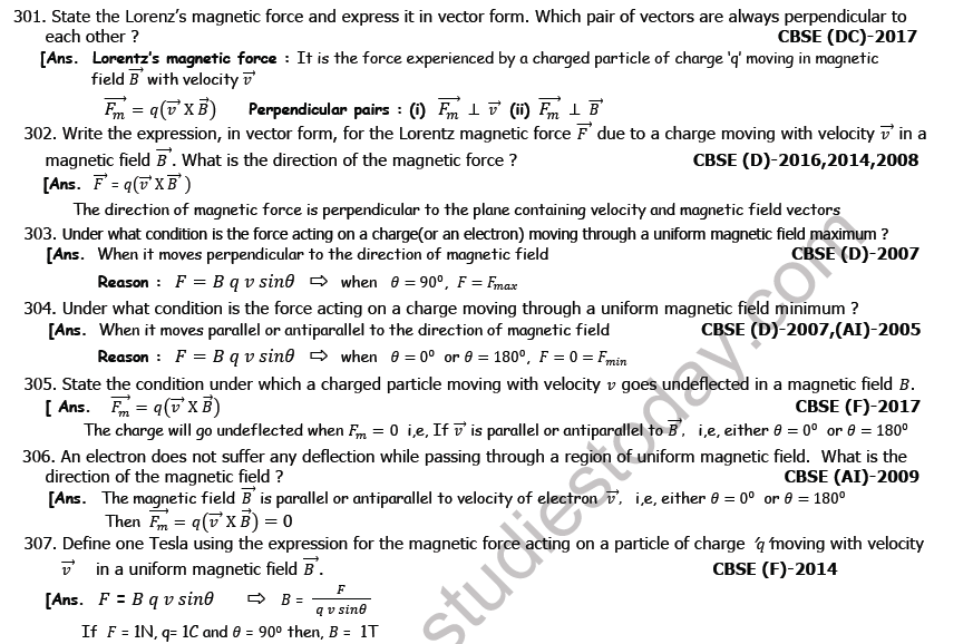
Question 301. State the Lorenz’s magnetic force and express it in vector form. Which pair of vectors are always perpendicular to each other ?
Answer: Lorentz magnetic force represents the force felt by a charge carrier of value \( q \) as it travels through an external magnetic field \( \vec{B} \) at a velocity of \( \vec{v} \).
Its vector representation is:
\[ \vec{F}_m = q(\vec{v} \times \vec{B}) \delta ]
The following vector pairs must always be orthogonal to one another:
(i) The magnetic force vector and the velocity vector, i.e., \( \vec{F}_m \perp \vec{v} \).
(ii) The magnetic force vector and the magnetic field vector, i.e., \( \vec{F}_m \perp \vec{B} \).
In simple words: Lorentz force is the magnetic push felt by a moving charge. This push is always perpendicular to both the direction the charge is moving and the direction of the magnetic field.
Exam Tip: Clearly state that the force is perpendicular to the plane containing both \( \vec{v} \) and \( \vec{B} \).
Question 302. Write the expression, in vector form, for the Lorentz magnetic force due to a charge moving with velocity in a magnetic field . What is the direction of the magnetic force ?
Answer: The vector form of the magnetic force acting on a moving charge is:
\[ \vec{F} = q(\vec{v} \times \vec{B}) \]
The direction of this force vector \( \vec{F} \) is always oriented perpendicular to the plane containing both the velocity vector \( \vec{v} \) and the magnetic field vector \( \vec{B} \), determined by the right-hand rule.
In simple words: The formula for this force is \( \vec{F} = q(\vec{v} \times \vec{B}) \). The force always points perpendicular to the flat sheet formed by the velocity and magnetic field arrows.
Exam Tip: Mention the right-hand rule explicitly as the method used to find the exact direction of the cross product.
Question 303. Under what condition is the force acting on a charge(or an electron) moving through a uniform magnetic field maximum ?
Answer: The magnetic force experienced by the charge is maximized when its velocity vector is perpendicular to the direction of the magnetic field.
**Reason**: The magnitude of the Lorentz force is given by:
\[ F = B q v \sin\theta \]
Where \( \theta \) is the angle between \( \vec{v} \) and \( \vec{B} \). The sine function reaches its maximum value of \( 1 \) when \( \theta = 90^\circ \).
\( \implies F_{\text{max}} = B q v \)
This occurs when the movement is strictly perpendicular to the field.
In simple words: The force is strongest when the charge travels at exactly a 90-degree angle to the magnetic field lines.
Exam Tip: Show the equation \( F = B q v \sin\theta \) and substitute \( \theta = 90^\circ \) to secure full marks.
Question 304. Under what condition is the force acting on a charge moving through a uniform magnetic field minimum ?
Answer: The magnetic force acting on the moving charge reaches its minimum value of zero when the motion is either parallel or antiparallel to the magnetic field lines.
**Reason**: According to the relation:
\[ F = B q v \sin\theta \]
When the particle moves along the direction of the field (\( \theta = 0^\circ \)) or directly opposite to it (\( \theta = 180^\circ \)), we have \( \sin 0^\circ = \sin 180^\circ = 0 \).
\( \implies F_{\text{min}} = 0 \)
Thus, no magnetic force acts on the charge.
In simple words: The force is zero if the charge moves in the exact same direction as the magnetic field or directly opposite to it.
Exam Tip: Remember to state both parallel (\( \theta = 0^\circ \)) and antiparallel (\( \theta = 180^\circ \)) conditions to get full credit.
Question 305. State the condition under which a charged particle moving with velocity goes undeflected in a magnetic field .
Answer: A charged particle passing through a magnetic field will travel in a straight line without any deflection if the net magnetic force acting on it is zero.
The magnetic force is expressed as:
\[ \vec{F}_m = q(\vec{v} \times \vec{B}) \]
The force vanishes (\( \vec{F}_m = 0 \)) when the velocity vector \( \vec{v} \) is aligned parallel or antiparallel to the magnetic field vector \( \vec{B} \). This happens when the angle \( \theta \) between them is either \( 0^\circ \) or \( 180^\circ \).
In simple words: The particle won't bend if it travels straight along the magnetic field lines, either in the same direction or the opposite direction.
Exam Tip: Make sure to write down the vector cross-product equation to show why the force becomes zero mathematically.
Question 306. An electron does not suffer any deflection while passing through a region of uniform magnetic field. What is the direction of the magnetic field ?
Answer: Since the electron moves undeflected, the magnetic force acting on it must be zero. This requires the magnetic field \( \vec{B} \) to be aligned parallel or antiparallel to the velocity vector \( \vec{v} \) of the electron, meaning the angle between them is either \( 0^\circ \) or \( 180^\circ \). Under this condition:
\[ \vec{F}_m = -e(\vec{v} \times \vec{B}) = 0 \]
Therefore, the magnetic field is directed along or opposite to the line of motion of the electron.
In simple words: The magnetic field must point in the exact same direction the electron is moving, or in the exact opposite direction.
Exam Tip: Specifying both parallel and antiparallel directions is necessary for a complete and correct answer.
Question 307. Define one Tesla using the expression for the magnetic force acting on a particle of charge moving with velocity in a uniform magnetic field .
Answer: Using the expression for magnetic force:
\[ F = B q v \sin\theta \]
We can express the magnetic field \( B \) as:
\[ B = \frac{F}{q v \sin\theta} \]
If a charge of \( q = 1\text{ C} \) moves with a velocity of \( v = 1\text{ m/s} \) perpendicular to the magnetic field (\( \theta = 90^\circ \)), and experiences a force of \( F = 1\text{ N} \), then the field strength is:
\[ B = \frac{1\text{ N}}{(1\text{ C})(1\text{ m/s})(1)} = 1\text{ T} \]
One Tesla is therefore defined as the strength of a uniform magnetic field in which a \( 1\text{ Coulomb} \) charge moving at \( 1\text{ m/s} \) perpendicular to the field experiences a force of exactly \( 1\text{ Newton} \).
In simple words: One Tesla is the amount of magnetic field that exerts a 1-Newton force on a 1-Coulomb charge moving at 1 meter per second perpendicular to the field.
Exam Tip: Do not forget to include the word "normally" or "perpendicularly" in your definition, as the sine of the angle must equal 1.
Question 308. A beam of \alpha - particles projected along + x axis, experiences a force due to magnetic field along the + y axis. What is the direction of magnetic field ?
Answer: The force is along the \( +y \)-axis (\( \vec{F} = F\hat{j} \)) and the velocity of the positively charged \( \alpha \)-particle is along the \( +x \)-axis (\( \vec{v} = v\hat{i} \)). Using the magnetic force equation:
\[ \vec{F} = q(\vec{v} \times \vec{B}) \]
Since \( \hat{i} \times (-\hat{k}) = \hat{j} \), the magnetic field vector \( \vec{B} \) must point along the **negative z-axis** (\( -\hat{k} \)). Therefore, the magnetic field is directed into the plane of the paper.
In simple words: Since the positively charged particle is moving right and feels an upward force, Fleming's left-hand rule shows that the magnetic field must point straight into the page (along the negative z-axis).
Exam Tip: Use Fleming's left-hand rule or vector cross products to determine the direction, and always state the axis clearly.
Question 309. A beam of electrons projected along + x axis, experiences a force due to magnetic field along the + y axis. What is the direction of magnetic field ?
Answer: Since an electron carries a negative charge (\( q = -e \)), its velocity is \( \vec{v} = v\hat{i} \), and the experienced force is along the \( +y \)-axis (\( \vec{F} = F\hat{j} \)). Utilizing the force equation:
\[ \vec{F} = q(\vec{v} \times \vec{B}) \]
\[ F\hat{j} = -e(v\hat{i} \times \vec{B}) \]
For the cross product, since \( \hat{i} \times \hat{k} = -\hat{j} \), we have \( -(\hat{i} \times \hat{k}) = \hat{j} \). Hence, the magnetic field \( \vec{B} \) must point along the **positive z-axis** (\( +\hat{k} \)).
In simple words: An electron has a negative charge, which reverses the force direction. For a rightward-moving electron to feel an upward force, the magnetic field must point straight out of the page (along the positive z-axis).
Exam Tip: Always account for the negative charge of an electron when using vector cross products or Fleming's left-hand rule.
Question 310. A beam of protons projected along + x axis, experiences a force due to magnetic field along the – y axis. What is the direction of magnetic field ?
Answer: Protons carry a positive charge (\( q = +e \)). Their velocity is along the \( +x \)-axis (\( \vec{v} = v\hat{i} \)), and the magnetic force is directed along the \( -y \)-axis (\( \vec{F} = -F\hat{j} \)). Using the cross-product relation:
\[ \vec{F} = q(\vec{v} \times \vec{B}) \]
Since \( \hat{i} \times \hat{k} = -\hat{j} \), the magnetic field vector \( \vec{B} \) must be oriented along the **positive z-axis** (\( +\hat{k} \)).
In simple words: Since protons are positive, a rightward motion and a downward force mean the magnetic field must point straight out of the page (along the positive z-axis).
Exam Tip: Ensure your vector notation is precise, clearly showing how the cross product \( \hat{i} \times \hat{k} \) gives \( -\hat{j} \).
Question 311. Two particles A and B of masses m and 2m have charges q and 2q respectively. Both these particles moving with velocities \( v_1 \) and \( v_2 \) respectively in the same direction enter the same magnetic field acting normally to the direction of their motion. If the two forces \( F_A \) and \( F_B \) acting on them are in the ratio of 1:2, find the ratio of their velocities.
Answer: The magnetic force experienced by a charged particle moving perpendicular to a magnetic field is:
\[ F = B q v \sin 90^\circ = B q v \]
Taking the ratio of the forces for particles A and B:
\[ \frac{F_A}{F_B} = \frac{B q_A v_1}{B q_B v_2} \]
Substitute the given values \( q_A = q \), \( q_B = 2q \), and \( \frac{F_A}{F_B} = \frac{1}{2} \):
\[ \frac{1}{2} = \frac{q v_1}{2q v_2} \]
\[ \frac{1}{2} = \frac{v_1}{2 v_2} \]
\( \implies \frac{v_1}{v_2} = \frac{1}{1} \)
Therefore, the ratio of their velocities \( v_1 : v_2 \) is \( 1:1 \).
In simple words: Since the force depends on both the charge and the speed, and the second particle has twice the charge and feels twice the force, their speeds must be exactly the same.
Exam Tip: Note that the masses of the particles do not affect the magnetic force acting on them, so the mass values are extra information.
Question 311a. When a charged particle moving with velocity is subjected to a magnetic field , the force acting on it is non zero. Would the particle gain any energy ?
Answer: No, the charged particle will not gain any kinetic energy.
**Reason**: The magnetic force \( \vec{F}_m = q(\vec{v} \times \vec{B}) \) is always perpendicular to the velocity vector \( \vec{v} \) of the particle. Because the force is orthogonal to the direction of displacement at any instant, the power delivered and the work done by the magnetic force are always zero:
\[ W = \int \vec{F}_m \cdot d\vec{r} = 0 \]
According to the work-energy theorem, since no work is performed by the magnetic field, the kinetic energy of the particle remains constant.
In simple words: No, the particle does not gain energy. The magnetic force always pushes sideways (perpendicular to the motion), so it only changes the particle's direction, not its speed or energy.
Exam Tip: Use the work-energy theorem to explain why the constant speed of a particle in a magnetic field prevents any energy gain.
Question 311b. In a certain region of space, electric field and magnetic field are perpendicular to each other. An electron enters in the region perpendicular to the direction of both and and moves undeflected. Find the velocity of electron.
Answer: For the electron to travel through the crossed electric and magnetic fields without any deflection, the electric force and the magnetic force acting on it must be equal in magnitude and opposite in direction:
\[ F_e = F_m \]
Substitute the magnitude of both forces:
\[ e E = e v B \]
Solving for the velocity \( v \):
\( \implies v = \frac{E}{B} \)
This is the velocity selector condition.
In simple words: For the electron to go straight, the electric pull must perfectly balance the magnetic push. This happens when the electron's speed is exactly the electric field strength divided by the magnetic field strength.
Exam Tip: This velocity-selection principle \( v = E/B \) is fundamental for understanding devices like mass spectrometers and cyclotrons.
Question 311c. A long straight wire carries a steady current along the positive y-axis in a coordinate system. A particle of charge is moving with a velocity along the x-axis. In which direction will the particle experience a force ?
Answer: The current flowing along the positive \( y \)-axis creates a magnetic field \( \vec{B} \) pointing into the page (along the negative \( z \)-axis, \( -\hat{k} \)) in the region of the positive \( x \)-axis.
The charge \( +q \) moves along the positive \( x \)-axis with velocity \( \vec{v} = v\hat{i} \). The magnetic force is:
\[ \vec{F} = q(\vec{v} \times \vec{B}) = q(v\hat{i} \times B(-\hat{k})) = qvB\hat{j} \]
Therefore, the force acts along the **positive y-axis**.
In simple words: The current in the wire creates a magnetic field pointing into the page. When the positive charge moves right through this field, the magnetic force pushes it upward along the positive y-axis.
Exam Tip: First find the direction of the magnetic field using the right-hand grip rule, then find the force direction using the cross-product rule.
Question 311d. What will be the path of a charged particle moving perpendicular to a uniform magnetic field ?
Answer: The trajectory of the charged particle will be a **circular path** because the magnetic force acts as a centripetal force, remaining perpendicular to the velocity at every point of its motion.
In simple words: The path is a perfect circle because the magnetic field constantly pulls the charge sideways, acting just like a string swinging a ball around.
Exam Tip: Mention that the speed remains constant while the velocity's direction changes continuously.
Question 311e. What will be the path of a charged particle moving in a uniform magnetic field at any arbitrary angle ?
Answer: The path of the charged particle will be a **helical path** (or helix).
In simple words: The particle moves in a spiral (helical) path, looping like a spring along the direction of the magnetic field.
Exam Tip: Explain that the velocity component parallel to the field keeps the particle moving forward, while the perpendicular component makes it spin in a circle.
Question 311f. What can be the cause of helical motion of a charged particle ?
Answer: Helical motion occurs when a charged particle enters a magnetic field at an angle \( \theta \) other than \( 0^\circ \), \( 180^\circ \), or \( 90^\circ \). Under this condition, the velocity has two components:
(i) A component perpendicular to the field (\( v\sin\theta \ )), which produces a circular motion.
(ii) A component parallel to the field (\( v\cos\theta \ )), which is unaffected by the magnetic force and moves the particle forward along the field lines.
The combination of these two motions results in a helix.
In simple words: This spiral path is caused by the velocity being at an angle. One part of the speed spins the particle in a circle, while the other part slides it forward along the field lines.
Exam Tip: Clearly identify both the parallel and perpendicular components of velocity to explain the cause of helical motion comprehensively.
Question 312. State Biot – Savart law and express this law in the vector form.
Answer: Biot-Savart law states that the magnetic field \( d\vec{B} \) produced by a small current-carrying element \( I d\vec{l} \) at a point with position vector \( \vec{r} \) depends on the following factors:
(i) It is directly proportional to the current element \( I d\vec{l} \).
(ii) It is inversely proportional to the square of the distance \( r^2 \) from the element.
(iii) It is directly proportional to the sine of the angle \( \theta \) between the current element and the position vector.
Combining these factors gives:
\[ dB \propto \frac{I dl \sin\theta}{r^2} \implies dB = \frac{\mu_0}{4\pi} \frac{I dl \sin\theta}{r^2} \]
In vector notation, the law is written as:
\[ d\vec{B} = \frac{\mu_0}{4\pi} \frac{I (d\vec{l} \times \vec{r})}{r^3} \]
Where \( \mu_0 \) is the permeability of free space.
In simple words: The Biot-Savart law calculates the magnetic field from a tiny piece of wire. It shows that the magnetic field gets stronger with more current and weaker as you move further away, pointing perpendicular to both the wire and the line connecting them.
Exam Tip: Ensure you use \( r^3 \) in the denominator when expressing the law in vector form, as the unit vector \( \hat{r} \) is replaced by \( \vec{r} \).
Question 313. A current I flows in a conductor placed perpendicular to the plane of the paper. Indicate the direction of the magnetic field due to a small element at point situated at a distance from the element as shown in figure.
Answer: Let the current element point out of the page along the positive \( z \)-axis (\( I d\vec{l} = I dl \hat{k} \)). The position vector of the point is along the positive \( y \)-axis (\( \vec{r} = r\hat{j} \)).
Applying the Biot-Savart law in vector form:
\[ d\vec{B} = \frac{\mu_0}{4\pi} \frac{I (d\vec{l} \times \vec{r})}{r^3} \]
Substitute the unit vectors:
\[ d\vec{B} = \frac{\mu_0}{4\pi} \frac{I dl \hat{k} \times r \hat{j}}{r^3} \]
Since \( \hat{k} \times \hat{j} = -\hat{i} \), we get:
\[ d\vec{B} = \frac{\mu_0 I dl}{4\pi r^2} (-\hat{i}) \]
Consequently, the magnetic field points along the **negative x-direction**.
In simple words: If the wire's current comes straight out of the page and you look at a point directly above it, the magnetic field points straight to the left (along the negative x-axis).
Exam Tip: Show the unit vector cross-product calculation clearly to justify your directional answer.
Question 314. Write, using Biot – Savart’s law, the expression for the magnetic field due to an element carrying current I at a distance from it in a vector form.
Answer: According to the Biot-Savart law, the magnetic field vector \( d\vec{B} \) produced by a current-carrying element \( I d\vec{l} \) at a displacement \( \vec{r} \) is:
\[ d\vec{B} = \frac{\mu_0}{4\pi} \frac{I (d\vec{l} \times \vec{r})}{r^3} \]
This can also be expressed using the unit vector \( \hat{r} \) as:
\[ d\vec{B} = \frac{\mu_0}{4\pi} \frac{I (d\vec{l} \times \hat{r})}{r^2} \]
In simple words: The vector formula is \( d\vec{B} = \frac{\mu_0}{4\pi} \frac{I (d\vec{l} \times \vec{r})}{r^3} \), which gives both the strength and direction of the magnetic field.
Exam Tip: Clearly define the term \( \mu_0 \) as the permeability of free space to present a complete answer.
Question 315. State Ampere’s circuital law.
Answer: Ampere's circuital law states that the line integral of the magnetic field vector \( \vec{B} \) around any closed path (Amperian loop) is equal to \( \mu_0 \) times the net current \( I \) passing through the surface enclosed by that loop:
\[ \oint \vec{B} \cdot d\vec{l} = \mu_0 I \ ]
Here, \( \mu_0 \) is the permeability of free space.
In simple words: If you trace a closed loop around some electric currents and add up the magnetic field along that path, the total will always equal \( \mu_0 \) times the current passing through the loop.
Exam Tip: Do not forget to write down the closed loop integral symbol \( \oint \) to represent the line integral properly.
Question 315a. What is the source of magnetic field (or magnetism) ?
Answer: The primary source of magnetism is the motion of electric charges. Within atoms, the orbital revolution and spin of electrons act as microscopic current loops, which generate local magnetic fields.
In simple words: Magnetism is created by moving electric charges. Inside materials, electrons spinning and orbiting around atomic nuclei act like tiny circular currents, creating their own magnetic fields.
Exam Tip: Mention both the orbital motion and spin of electrons to give a complete explanation of atomic magnetism.
Question 316. Does a magnetic monopole exists ? Justify your answer.
Answer: No, isolated magnetic monopoles do not exist in nature. Every magnet must have both a north pole and a south pole. This is because magnetic fields are generated by closed loops of current rather than by individual magnetic charges, meaning magnetic field lines always form continuous closed loops.
In simple words: No. You can never have a North pole without a South pole. Magnetism is created by charges moving in loops, which always creates two opposite sides (poles) at the same time.
Exam Tip: Support your answer by mentioning Gauss's law for magnetism, which states that the net magnetic flux through any closed surface is always zero.
Question 317. Draw the magnetic field lines due to a circular wire carrying current .
Answer: The magnetic field lines form concentric circles around each section of the circular wire, passing straight through the center of the loop in a direction perpendicular to its plane.
In simple words: The magnetic field lines form small concentric circles directly around the wire, while passing straight through the center of the loop in a uniform direction.
Exam Tip: Ensure your diagram shows the field lines passing straight through the center of the loop, getting more curved and circular closer to the wire.
Question 318. How are the magnetic field lines different from the electrostatic field lines ?
Answer: The primary difference lies in their continuity:
- **Magnetic field lines** form continuous, unbroken closed loops that run from the north pole to the south pole outside a magnet, and from south to north inside it.
- **Electrostatic field lines** are discontinuous; they begin at positive charges and terminate at negative charges, never forming closed loops.
In simple words: Magnetic field lines are continuous loops that have no beginning or end. Electric field lines start at a positive charge and stop at a negative charge, like open-ended paths.
Exam Tip: Mention that the non-existence of magnetic monopoles is the fundamental reason why magnetic field lines must form closed loops.
Question 319. Why do magnetic field lines for continuous closed loops ?
Answer: Magnetic field lines must form continuous closed loops because isolated magnetic monopoles do not exist. Since magnets are always dipoles with equal and opposite poles, the net magnetic flux exiting any closed volume is always zero, forcing every line that leaves a magnet to return to it.
In simple words: Since you can never separate North and South poles, any magnetic field line that shoots out of a North pole has to loop all the way back into a South pole.
Exam Tip: Relate this property directly to Gauss's law for magnetism: \( \oint \vec{B} \cdot d\vec{A} = 0 \).
Question 320. Can two magnetic lines of force intersect each other. Justify your answer.
Answer: No, magnetic field lines can never cross one another.
**Justification**: The tangent to a field line at any point indicates the direction of the net magnetic field at that location. If two lines were to intersect, one could draw two distinct tangents at the crossing point. This would imply that the magnetic field has two different directions at a single point, which is physically impossible.
In simple words: No. If they crossed, a compass placed at the crossing point would have to point in two directions at the same time, which cannot happen.
Exam Tip: Use the concept of a unique tangent direction to explain why crossing field lines is physically impossible.
Question 321. Magnetic field lines can be entirely confined within the core of a toroid, but not within a straight solenoid. Why ?
Answer: Since a toroid is formed as a continuous, closed circular ring, it has no ends, allowing its magnetic field lines to form complete closed loops entirely inside its core. Conversely, a straight solenoid has two distinct open ends. Because magnetic field lines must be continuous closed loops, they cannot stay trapped inside a finite straight tube; they must emerge from one end and loop around the outside to re-enter the other end.
In simple words: A toroid is a closed circle with no ends, so the magnetic loops can stay trapped inside it forever. A solenoid is like a straight pipe with open ends, so the magnetic lines must leak out and loop back around.
Exam Tip: Frame your answer around the requirement of "continuous closed loops" to show complete physical reasoning.
Question 322. Depict magnetic field lines due to two straight, long, parallel conductors carrying steady currents and in the (i) same direction, (ii) opposite direction.
Answer: The magnetic field lines wrap around the parallel conductors in concentric loops. For currents in the same direction, the outer loops merge and pull the wires together. For opposite currents, the field lines crowd between the wires and push them apart.
In simple words: (i) When currents flow in the same direction, the magnetic field lines wrap around both wires together, pulling them in. (ii) When they flow in opposite directions, the individual field lines crowd and push against each other between the wires, pushing them apart.
Exam Tip: Use dots (out of page) and crosses (into page) to represent current directions clearly in your exam sketches.
Question 323. Using the concept of force between two infinitely long parallel current carrying conductors, define one ampere of current.
Answer: One Ampere represents the constant current which, if maintained in two infinitely long, straight, parallel conductors of negligible circular cross-section, placed exactly \( 1\text{ meter} \) apart in a vacuum, produces a mutual magnetic force of exactly \( 2 \times 10^{-7}\text{ Newtons} \) per meter of length on each conductor.
In simple words: One Ampere is the specific amount of current that, when flowing through two parallel wires spaced 1 meter apart in space, creates a magnetic pull of 2 × 10^-7 Newtons on every meter of wire.
Exam Tip: Be sure to mention "free space" or "vacuum" and specify the exact force value \( 2 \times 10^{-7}\text{ N/m} \) to get full marks.
Question 324. How is the magnetic field inside a given solenoid made strong ?
Answer: The magnetic field strength inside a solenoid can be enhanced through three main methods:
(i) **Winding Density**: Increasing the total number of turns per unit length (\( n \)) of the coil.
(ii) **Current Level**: Boosting the amount of electrical current (\( I \)) flowing through the wire.
(iii) **Core Material**: Inserting a high-permeability ferromagnetic core, such as soft iron, inside the hollow space of the solenoid.
In simple words: You can make a solenoid's magnet stronger by packing more wire loops closer together, running more current through it, or sliding a soft iron rod into its center.
Exam Tip: List all three factors clearly and state the formula \( B = \mu n I \) (or \( B = \mu_0 \mu_r n I \)) to back up your points.
Question 325. Write the expression for Lorentz’s magnetic force on a particle of charge moving with velocity in a magnetic field . Show that no work is done by this force on the charged particle.
Answer: The vector equation for the Lorentz magnetic force on a charge \( q \) is:
\[ \vec{F}_m = q(\vec{v} \times \vec{B}) \]
To prove that the work done by this force is zero:
The rate of doing work (power \( P \)) is given by the dot product of the force and velocity vectors:
\[ P = \vec{F}_m \cdot \vec{v} \]
Substitute the expression for \( \vec{F}_m \):
\[ P = q(\vec{v} \times \vec{B}) \cdot \vec{v} \]
By vector identities, the cross product \( (\vec{v} \times \vec{B}) \) results in a vector that is perpendicular to both \( \vec{v} \) and \( \vec{B} \). Thus:
\[ (\vec{v} \times \vec{B}) \perp \vec{v} \implies (\vec{v} \times \vec{B}) \cdot \vec{v} = 0 \]
Since power is zero, the work done \( W \) over any displacement is also zero:
\[ W = \int P dt = 0 \]
Therefore, the magnetic force performs no work on the moving charge.
In simple words: The magnetic force is always perpendicular to the direction the charge is moving. Because you only do work when you push in the direction of motion, a perpendicular push does zero work.
Exam Tip: Use the vector property of dot products with perpendicular vectors to prove this relation elegantly in your answer.
Question 326. Which one of the following will experience maximum force, when projected with the same velocity perpendicular to the Magnetic field : (i) \alpha - particle, and (ii) \beta - particle ?
Answer: When projected perpendicular to a magnetic field (\( \theta = 90^\circ \)), the magnetic force is:
\[ F_m = B q v \]
For particles moving at the same speed \( v \) in the same field \( B \), the force is directly proportional to the magnitude of the charge \( q \):
- The \( \alpha \)-particle carries a charge of \( q_{\alpha} = +2e \).
- The \( \beta \)-particle (electron) carries a charge of \( q_{\beta} = -e \) (magnitude \( e \)).
Taking the ratio of the forces:
\[ \frac{F_{\alpha}}{F_{\beta}} = \frac{2e}{e} = 2 \implies F_{\alpha} = 2 F_{\beta} \]
Therefore, the **\( \alpha \)-particle** experiences the maximum force.
In simple words: The magnetic force depends on the charge. Since an alpha particle has twice the charge of a beta particle, it feels twice as much force when they travel at the same speed.
Exam Tip: Clearly state the relative charges of both particles (\( 2e \) vs \( e \)) to justify your force ratio calculation.
Question 327. Find the condition under which the charged particles moving with different speeds in the presence of electric and magnetic field vectors can be used to select charged particles of a particular speed.
Answer: To select charged particles of a specific speed, we use a crossed-field arrangement (velocity selector):
(i) **Orthogonal Fields**: The velocity vector \( \vec{v} \), the electric field \( \vec{E} \), and the magnetic field \( \vec{B} \) must be mutually perpendicular to one another.
(ii) **Balanced Forces**: For a particle to pass through without being deflected, the electric force must balance the magnetic force:
\[ F_e = F_m \implies q E = q v B \]
\( \implies v = \frac{E}{B} \)
Only particles with this exact velocity \( v \) will travel in a straight line, while others will be deflected away.
In simple words: If we set up electric and magnetic fields pointing at right angles to each other, they will pull a moving charge in opposite directions. Only charges traveling at speed \( v = E/B \) will have perfectly balanced forces and pass straight through.
Exam Tip: State both conditions (perpendicularity and the balanced force equation) to ensure your answer is complete.
Question 328. A charge 'q' moving along the x axis with velocity \vec{v} is subjected to a uniform magnetic field B acting along the z axis as it crosses the origin 0. (i) Trace its trajectory. (ii) Does the charge gain kinetic energy as it enters the magnetic field ? Justify your answer.
Answer: (i) **Trajectory**: The charge enters with velocity along the \( +x \)-axis (\( \vec{v} = v\hat{i} \)) in a magnetic field along the \( +z \)-axis (\( \vec{B} = B\hat{k} \)). The magnetic force is:
\[ \vec{F}_m = q(v\hat{i} \times B\hat{k}) = -q v B \hat{j} \]
As it passes the origin, the force pulls it toward the negative \( y \)-direction. Since this force is perpendicular to its velocity, the particle will describe a **circular path in the XY-plane** going clockwise.
(ii) **Energy Gain**: No, the charge does not gain any kinetic energy. Because the magnetic force \( \vec{F}_m \) is always perpendicular to the velocity \( \vec{v} \), the work done by the magnetic field is zero. By the work-energy theorem, since no work is performed, the kinetic energy remains completely constant.
In simple words: (i) As the charge crosses the origin, the magnetic field pushes it down along the y-axis, making it loop in a circular path in the XY plane. (ii) No energy is gained because the force only turns the particle without speeding it up.
Exam Tip: Clearly show the circular arc in your diagram starting from the origin and heading into the fourth quadrant (towards negative y) to display correct physical conventions.
Question 329. (a) A point charge q moving with speed v enters a uniform magnetic field B that is acting into the plane of the paper as shown. What is the path followed by the charge q and in which plane does it move ?
(b) How does the path followed by the charge get affected if its velocity has a component parallel to B ?
(c) If an electric field E is also applied such that the particle continues moving along the original straight line path, what should be the magnitude and direction of the electric field ?
Answer: (a) **Circular Path**: Since the velocity is perpendicular to the inward magnetic field, the point charge \( q \) will describe a **circular trajectory** in the XY-plane in an anticlockwise direction.
(b) **Helical Path**: If the velocity has a component parallel to the magnetic field \( \vec{B} \), this parallel component is unaffected by the magnetic force and moves the particle forward along the field lines, while the perpendicular component makes it spin. This combined motion makes the trajectory **helical**.
(c) **Electric Field**: The magnetic force points along the negative \( y \)-direction (\( \vec{F}_m = -q v B \hat{j} \)). For the particle to continue moving in a straight line, we must apply an electric field \( \vec{E} \) to create an equal and opposite force along the positive \( y \)-direction:
\[ \vec{F}_e = -\vec{F}_m \implies q E = q v B \]
\( \implies E = B v \)
The electric field must have a magnitude of \( E = B v \) and be directed along the **positive y-axis** (\( +y \) direction).
In simple words: (a) The charge goes in an anticlockwise circle in the XY plane. (b) If it has forward speed along the field lines, it spirals like a spring (helix). (c) To balance this and go straight, we need an upward electric field of strength \( E = Bv \).
Exam Tip: For part (c), clearly specify both the magnitude \( E = B v \) and its direction along the \( +y \) axis to ensure a complete answer.
Question 330. Uniform electric and magnetic fields are produced pointing in the same direction. An electron is projected in the direction of the fields. What will be the effect on the kinetic energy of electron due to two fields?
Answer: The uniform fields are parallel to the direction of motion (\( \theta = 0^\circ \)):
- **Effect of Magnetic Field**: Since the electron moves parallel to the magnetic field, the angle \( \theta \) is \( 0^\circ \). The magnetic force is:
\[ F_m = -e v B \sin 0^\circ = 0 \]
Thus, the magnetic field exerts no force and has **no effect on the kinetic energy** of the electron.
- **Effect of Electric Field**: Since the electron is negatively charged, the electric field \( \vec{E} \) exerts a retarding force \( \vec{F}_e = -e\vec{E} \) opposite to its direction of motion. This force decelerates the electron, causing its **kinetic energy to decrease**.
In simple words: The magnetic field does nothing because the electron is traveling along the field lines. However, the electric field pulls back on the negative electron, slowing it down and reducing its kinetic energy.
Exam Tip: Be sure to explain why the magnetic force is zero, and how the electric force opposes the velocity of the negatively charged electron.
Question 331. A particle of charge 'q' and mass 'm' is moving with velocity \vec{v}. It is subjected to a uniform magnetic field \vec{B} directed perpendicular to its velocity. Show that it describes a circular path. Obtain the expression for its radius and show that frequency of revolution is independent of velocity.
Answer: **Circular Motion**: When a charged particle moves perpendicular to a uniform magnetic field, the magnetic force \( F_m = q v B \) is always perpendicular to its velocity \( \vec{v} \). This sideways force acts as a centripetal force without changing the speed of the particle, forcing it to travel in a circular path.
**Radius of Path**: Equating the magnetic force to the centripetal force:
\[ \frac{m v^2}{r} = q v B \]
Solving for the radius \( r \):
\( \implies r = \frac{m v}{q B} \)
**Frequency of Revolution**: The time period \( T \) for one complete revolution is:
\[ T = \frac{2\pi r}{v} \]
Substitute the expression for \( r \):
\[ T = \frac{2\pi \left(\frac{m v}{q B}\right)}{v} = \frac{2\pi m}{q B} \]
The frequency of revolution \( f_c \) is the reciprocal of the time period:
\[ f_c = \frac{1}{T} = \frac{q B}{2\pi m} \]
Since the speed \( v \) does not appear in this final expression, the frequency of revolution is completely independent of the velocity of the particle.
In simple words: The magnetic force acts like a centripetal force, curving the particle into a circle. The radius of this circle is \( r = \frac{mv}{qB} \). Because a faster particle travels along a larger circle, the total time to complete a loop stays the same, meaning the frequency is independent of speed.
Exam Tip: Highlight the final formula \( f_c = \frac{q B}{2\pi m} \) and explicitly state that the velocity term \( v \) cancels out during the derivation.
Question 332. A charged particle moving in a straight line is accelerated by a potential difference V. It enters a uniform magnetic field B perpendicular to its path. Deduce in terms of V an expression for the radius of the circular path in which it travels.
Answer: When the charged particle of charge \( q \) and mass \( m \) is accelerated through a potential difference \( V \), its gained kinetic energy \( E_k \) is:
\[ E_k = \frac{1}{2} m v^2 = q V \]
This gives the velocity of the particle as:
\[ v = \sqrt{\frac{2 q V}{m}} \]
When it enters the perpendicular magnetic field \( B \), it undergoes circular motion with a radius \( r \):
\[ r = \frac{m v}{q B} \]
Substitute the expression for \( v \) into the radius equation:
\[ r = \frac{m}{q B} \sqrt{\frac{2 q V}{m}} = \frac{1}{B} \sqrt{\frac{2 m V}{q}} \]
This is the required expression for the radius in terms of the accelerating potential \( V \).
In simple words: The voltage speeds up the charge, giving it a velocity of \( v = \sqrt{\frac{2qV}{m}} \). When it loops inside the magnetic field, its path radius can be written as \( r = \frac{1}{B}\sqrt{\frac{2mV}{q}} \).
Exam Tip: Be careful to distinguish between the capital \( V \) for potential difference and the lowercase \( v \) for velocity in your equations.
Question 333. A uniform magnetic field is set up along the positive x-axis. A particle of charge ‘q’ and mass ‘m’ moving with a velocity \vec{v} enters the field at the origin in X-Y plane such that it has velocity components both along and perpendicular to the magnetic field Trace, giving reason, the trajectory followed by the particle. Find out the expression for the distance moved by the particle along the magnetic field in one rotation.
Answer: **Trajectory**: The trajectory followed by the particle is a **helix** along the \( x \)-axis.
**Reason**: The velocity of the particle has two components:
- The component perpendicular to the magnetic field (\( v_y \)) makes the particle move in a circular path within the YZ-plane.
- The component parallel to the magnetic field (\( v_x \)) experiences no magnetic force and keeps the particle moving forward along the \( x \)-axis at a constant speed.
The combination of these two movements results in a spiral or helical path.
**Distance in One Rotation (Pitch)**: The linear distance \( x \) traveled along the direction of the magnetic field in one time period \( T \) is:
\[ x = v_x \times T \]
Substitute \( T = \frac{2\pi m}{q B} \):
\[ x = v_x \left(\frac{2\pi m}{q B}\right) = \frac{2\pi m v_x}{q B} \]
This distance is called the pitch of the helix.
In simple words: One part of the speed spins the particle in a circle, while the other part pushes it straight along the x-axis, creating a spiral path. The distance it travels forward in one loop is \( \frac{2\pi m v_x}{qB} \).
Exam Tip: Define the distance traveled in one rotation as the "pitch of the helix" and show its formula clearly to score full marks.
Question 334. A charged particle enters a region of uniform magnetic field with its initial velocity directed (i) parallel to the field, and (ii) perpendicular to the field. Show that there is no change in kinetic energy of the particle in both cases.
Answer: (i) **Parallel projection (\( \theta = 0^\circ \))**:
The magnetic force acting on the particle is:
\[ F_m = q v B \sin 0^\circ = 0 \]
Since no force acts on the particle, both its velocity and its kinetic energy remain completely unchanged.
(ii) **Perpendicular projection (\( \theta = 90^\circ \))**:
The magnetic force \( \vec{F}_m = q(\vec{v} \times \vec{B}) \) acts perpendicular to the velocity \( \vec{v} \) at every instant. This means the force is perpendicular to the displacement \( d\vec{r} \), so:
\[ dW = \vec{F}_m \cdot d\vec{r} = 0 \]
By the work-energy theorem, the change in kinetic energy \( dK_e \) is equal to the work done:
\[ dK_e = dW = 0 \]
Thus, the kinetic energy of the particle remains constant in both cases.
In simple words: (i) If traveling parallel, the field exerts no force at all, so speed and energy stay the same. (ii) If traveling perpendicular, the force only bends the path without performing any work, keeping the energy constant.
Exam Tip: State the work-energy theorem explicitly to link the zero work done by the magnetic force to the conservation of kinetic energy.
Question 335. An \alpha - particle and a proton moving with the same speed, enter the same magnetic field region at right angles to the direction of the field. (i) Show the trajectories followed by the two particles in the region of the magnetic field.
(ii) Find the ratio of the radii of the circular paths which the two particles may describe.
Answer: (i) **Trajectories**: Both particles describe circular paths because they enter perpendicular to the magnetic field. Since both carry a positive charge, they bend in the same direction.
(ii) **Ratio of Radii**: The radius of a circular path in a magnetic field is:
\[ r = \frac{m v}{q B} \]
Since both particles have the same speed \( v \) and are in the same field \( B \), the radius is proportional to the mass-to-charge ratio \( \frac{m}{q} \):
\[ \frac{r_{\alpha}}{r_p} = \left(\frac{m_{\alpha}}{m_p}\right) \left(\frac{q_p}{q_{\alpha}}\right) \]
Using the relations \( m_{\alpha} = 4 m_p \) and \( q_{\alpha} = 2 q_p \):
\[ \frac{r_{\alpha}}{r_p} = \left(\frac{4 m_p}{m_p}\right) \left(\frac{q_p}{2 q_p}\right) = 4 \times \frac{1}{2} = 2 \]
Thus, the ratio of the radii of the circular paths \( r_{\alpha} : r_p \) is \( 2:1 \).
In simple words: Both particles loop in circles. Since the alpha particle is four times heavier but has only twice the charge, its circle is twice as large as the proton's circle.
Exam Tip: Clearly state the relative values of mass and charge for both particles (\( m_{\alpha} = 4m_p, q_{\alpha} = 2q_p \)) to make your derivation easy to follow.
Question 336. An electron and a proton moving parallel to each other in the same direction with equal momenta, enter in to a uniform magnetic field which is at right angles to their velocities. Trace their trajectories in the magnetic field.
OR
An electron and a proton moving with the same speed, enter the same magnetic field region at right angles to the direction of the field.
(i) Show the trajectories followed by the two particles in the region of the magnetic field.
(ii) Find the ratio of the radii of the circular paths which the two particles may describe.
Answer: (i) **Trajectories**: The proton (positive charge) and the electron (negative charge) will bend in opposite directions because of their opposite signs. The proton's trajectory will have a much larger radius than the electron's path.
(ii) **Ratio of Radii**: The radius of the circular path is:
\[ r = \frac{p}{q B} = \frac{m v}{q B} \]
Since the particles enter with equal speed \( v \) (or equal momentum \( p \)) and carry the same magnitude of charge \( q = e \):
\[ \frac{r_p}{r_e} = \frac{m_p}{m_e} \]
Since the mass of a proton is much greater than that of an electron (\( m_p \gg m_e \)), the radius of the proton's path is much larger than the electron's path (\( r_p \gg r_e \)).
In simple words: The electron and proton curve in opposite directions because they have opposite charges. The proton has a much larger path because it is much heavier than the tiny electron.
Exam Tip: Draw the two paths curving in opposite directions (one up, one down) and label them clearly to demonstrate the effect of charge polarity.
Question 337. A deuteron and a proton moving with the same speed, enter the same magnetic field region at right angles to the direction of the field.
(i) Show the trajectories followed by the two particles in the region of the magnetic field.
(ii) Find the ratio of the radii of the circular paths which the two particles may describe.
Answer: (i) **Trajectories**: Both particles are positively charged, so they bend in the same direction along circular paths.
(ii) **Ratio of Radii**: The circular path radius is:
\[ r = \frac{m v}{q B} \]
Since the speed \( v \) and field \( B \) are identical, the radius depends on the mass-to-charge ratio \( \frac{m}{q} \):
\[ \frac{r_d}{r_p} = \left(\frac{m_d}{m_p}\right) \left(\frac{q_p}{q_d}\right) \]
Since a deuteron has twice the mass of a proton (\( m_d \approx 2 m_p \)) and the same charge (\( q_d = q_p \)):
\[ \frac{r_d}{r_p} = \left(\frac{2 m_p}{m_p}\right) \left(\frac{q_p}{q_p}\right) = 2 \]
Thus, the ratio of the radii \( r_d : r_p \) is \( 2:1 \).
In simple words: Both curve in the same direction. Since a deuteron is twice as heavy as a proton but has the same charge, its circular path has twice the radius.
Exam Tip: Note that a deuteron consists of one proton and one neutron, giving it twice the mass of a single proton but the same net charge.
Question 338. A neutron, an electron and an alpha particle moving with equal velocities, enter a uniform magnetic field going Into the plane of the paper as shown. Trace their paths in the field and justify your answer.
Answer: When the particles enter the inward magnetic field:
- **Neutron**: Since a neutron has no electrical charge (\( q = 0 \)), it experiences no magnetic force (\( F_m = 0 \)). Consequently, it passes straight through without any deflection.
- **Alpha Particle**: Carrying a positive charge, its deflection direction is determined by Fleming's left-hand rule, causing it to curve upward in a circular path.
- **Electron**: Carrying a negative charge, it experiences a force in the opposite direction to the alpha particle, causing it to curve downward in a circular path.
In simple words: The neutron goes straight because it has no charge. The positive alpha particle curves upward, while the negative electron curves downward.
Exam Tip: Fleming's left-hand rule is the standard method used to find these deflection directions; explain its application clearly in your write-up.
Question 339. A proton and deuteron having equal momenta, enters a region of uniform magnetic field at right angles to the region of field. Find the ratio of the radii of curvature of the paths of the particles.
OR
A narrow beam of protons and deuterons, each having the same momentum, enters a region of uniform magnetic field directed perpendicular to their direction of momentum. What would be the ratio of the circular paths described by them ?
Answer: The radius of curvature of a charged particle's path in a magnetic field is:
\[ r = \frac{p}{q B} \]
Since both particles have the same momentum \( p \) and are in the same magnetic field \( B \), the radius is inversely proportional to their charge \( q \):
\[ r \propto \frac{1}{q} \]
Since both the proton and the deuteron carry the exact same charge (\( q_p = q_d = e \)), their path radii must be equal:
\[ \frac{r_p}{r_d} = \frac{q_d}{q_p} = \frac{e}{e} = 1 \]
Thus, the ratio of the radii of curvature \( r_p : r_d \) is \( 1:1 \).
In simple words: Even though the deuteron is heavier, their equal momentum and equal charge mean they will loop in circles of the exact same size.
Exam Tip: Highlight that when momentum \( p \) is constant, mass does not affect the radius, unlike the case where speed \( v \) is constant.
Question 340. Draw a neat labelled diagram of a cyclotron. State the underlying principle of a cyclotron. Show that time period of ions in cyclotron is independent of both the speed of ion and radius of circular path. Also obtain an expression for maximum kinetic energy gained by the particle.
Answer: **Cyclotron**: This is an electromagnetic device used to accelerate charged particles or ions to extremely high kinetic energies.
**Underlying Principle**: A charged particle is accelerated to high speeds by passing it repeatedly through a small region of high-frequency oscillating electric field. A strong perpendicular magnetic field keeps the particles revolving in circular paths within hollow metal semicircles (called Dees).
**Time Period Derivation**: The magnetic force provides the required centripetal force for circular motion:
\[ B q v = \frac{m v^2}{r} \implies r = \frac{m v}{q B} \]
The time period \( T \) for one complete revolution is:
\[ T = \frac{2\pi r}{v} = \frac{2\pi m}{q B} \]
Since the velocity \( v \) and radius \( r \) do not appear in this final expression, the time period is completely independent of both the speed of the ion and the radius of its path.
**Maximum Kinetic Energy**: The maximum radius of the path is equal to the outer radius \( r_0 \) of the Dees. The maximum velocity \( v_0 \) is:
\[ v_0 = \frac{q B r_0}{m} \]
The maximum kinetic energy \( E_{\text{k,max}} \) is:
\[ E_{\text{k,max}} = \frac{1}{2} m v_0^2 = \frac{1}{2} m \left(\frac{q B r_0}{m}\right)^2 = \frac{q^2 B^2 r_0^2}{2m} \]
This represents the maximum energy gained by the particle.
In simple words: A cyclotron uses an electric field to speed up particles and a magnetic field to bend them in circles. The time to complete a loop is always the same, regardless of speed. The maximum energy it can reach is \( \frac{q^2 B^2 r_0^2}{2m} \).
Exam Tip: Draw the two Dees clearly and include the high-frequency oscillator symbol in your diagram to secure full marks.
Question 341. Explain clearly the role of crossed electric and magnetic field in accelerating charge in a cyclotron
Answer: Inside a cyclotron, the two fields have separate, complementary functions:
(i) **Electric Field**: The oscillating electric field exists only in the narrow gap between the Dees and is used to accelerate the charged particle by giving it an energy boost each time it crosses the gap.
(ii) **Magnetic Field**: The static magnetic field acts perpendicular to the plane of the Dees and is used to guide the particle along a circular path, returning it to the gap repeatedly for further acceleration.
In simple words: The electric field acts in the gap to speed up the particle, while the magnetic field curves the particle in circles inside the metal Dees to bring it back to the gap over and over.
Exam Tip: Emphasize that the electric field does not exist inside the metal Dees due to electrostatic shielding.
Question 342. Where do the electric and magnetic fields exist in a Cyclotron. Write about their nature.
Answer: The fields are distributed and characterized as follows:
(i) **Electric Field**: It exists exclusively in the gap between the two Dees and is high-frequency alternating (oscillating) in nature.
(ii) **Magnetic Field**: It is applied uniformly across the entire region (both inside and outside the Dees) and is constant (static) and perpendicular in nature.
In simple words: The electric field is in the gap and constantly switches direction. The magnetic field is spread everywhere and stays constant to bend the particles.
Exam Tip: Clearly distinguish the alternating nature of the electric field from the constant nature of the magnetic field.
Question 343. What is resonance condition in a cyclotron ? How is it used to accelerate charged particles ?
Answer: **Resonance Condition**: This condition is met when the frequency of the applied alternating electric field is exactly equal to the frequency of revolution of the charged particle inside the Dees:
\[ f_{\text{osc}} = f_c = \frac{q B}{2\pi m} \]
**Application**: Achieving resonance ensures that every time the particle reaches the gap between the Dees, the polarity of the electric field reverses at that exact instant. This keeps the particle perfectly in phase with the electric field, allowing it to receive an accelerating push on every single crossing.
In simple words: Resonance means the electric field switches direction at the exact same rate the particle completes a half-circle. This ensures the particle always gets pushed in the right direction to speed up.
Exam Tip: Write the resonance equation \( f_{\text{osc}} = \frac{q B}{2\pi m} \) to explain this concept mathematically.
Question 344. What is the requirement of the frequency of the applied voltage so as to ensure that the ions get accelerated across the gap of the Dees in a cyclotron ?
Answer: To ensure continuous acceleration across the gap, the frequency of the applied alternating voltage must be perfectly matched to the cyclotron frequency of the ion:
\[ f = \frac{q B}{2\pi m} \]
This matching is essential to maintain phase synchronization.
In simple words: The voltage must alternate at the exact same frequency that the ions spin around the circle.
Exam Tip: State that this is called the "resonance frequency" of the cyclotron.
Question 345. In a cyclotron, the time period of ions is independent of both the speed of ion and radius of circular path. What is the significance of this property ?
Answer: This independence is the key operating feature of the cyclotron. Because the time period \( T = \frac{2\pi m}{q B} \) is constant regardless of how fast the particle is moving or how large its orbit becomes, a fixed-frequency oscillator can be used. This allows the particle to stay perfectly in sync with the accelerating electric field throughout its entire spiral path.
In simple words: This is important because it means we don't have to constantly change the speed of our electric switches as the particle goes faster and wider; a single constant frequency works for the whole run.
Exam Tip: Explain how this constancy is crucial for maintaining the "resonance condition" during the acceleration process.
Question 346. Is there an upper limit on the energy acquired by the particle ? Give reason.
Answer: Yes, there is a definite upper limit on the kinetic energy a particle can acquire in a cyclotron. This limit is reached when the radius of the particle's circular orbit becomes equal to the physical outer radius \( R \) of the Dees. At this boundary, the particle must be extracted, and its maximum energy is restricted to:
\[ E_{\text{k,max}} = \frac{q^2 B^2 R^2}{2m} \]
Additionally, at very high relativistic speeds, the mass of the particle increases, which throws it out of resonance with the oscillating field.
In simple words: Yes. The particle cannot grow its orbit wider than the actual physical size of the metal Dees, which limits its maximum speed and energy.
Exam Tip: Mention both the physical limit of the Dee radius \( R \) and the relativistic mass increase at high velocities as the two main limiting factors.
Question 347. Can we accelerate neutrons by a Cyclotron ? Give reason to your answer.
Answer: No, neutrons cannot be accelerated in a cyclotron.
**Reason**: Cyclotrons rely entirely on electric forces to speed up particles and magnetic forces to bend their paths. Since neutrons are electrically neutral (\( q = 0 \)), they do not experience any electromagnetic forces (\( \vec{F} = q(\vec{E} + \vec{v} \times \vec{B}) = 0 \)) and cannot be manipulated by the machine.
In simple words: No. Neutrons have no electric charge, so neither the electric field nor the magnetic field can push or bend them.
Exam Tip: State the Lorentz force equation to show why neutral particles experience zero electromagnetic force.
Question 348. Why is a Cyclotron not suitable for accelerating electrons ? Give reason.
Answer: A cyclotron is unsuitable for accelerating electrons due to their extremely small mass. When accelerated, electrons quickly reach relativistic speeds. According to Einstein's mass variation formula:
\[ m = \frac{m_0}{\sqrt{1 - \frac{v^2}{c^2}}} \]
This rapid speed increase causes a significant increase in their mass \( m \). This mass increase changes the time spent inside each Dee (\( t = \frac{\pi m}{q B} \)), causing the electrons to get out of phase with the oscillating electric field almost immediately.
In simple words: Electrons are so light that they speed up to near the speed of light almost instantly. This makes them heavier due to relativity, which throws them out of sync with the electric switches.
Exam Tip: Write down the relativistic mass formula \( m = \frac{m_0}{\sqrt{1 - v^2/c^2}} \) to provide a mathematically complete answer.
Question 349. Explain briefly, at very high speeds charged particle in a cyclotron can be thrown out of resonance. How this drawback can be overcome ?
Answer: At extremely high velocities, a particle's mass increases relativistically according to \( m = \frac{m_0}{\sqrt{1 - v^2/c^2}} \). This mass increase causes its frequency of revolution:
\[ f = \frac{q B}{2\pi m} \]
to decrease. As a result, the particle lags behind and is thrown out of phase (resonance) with the applied electric field.
This limitation can be resolved in two ways:
(i) **Synchrotron**: Increasing the magnetic field strength \( B \) dynamically as the particle's speed increases to keep the frequency constant.
(ii) **Synchro-cyclotron**: Decreasing the frequency of the alternating electric field progressively to match the decreasing revolution frequency of the heavier particle.
In simple words: At high speeds, particles get heavier and take longer to complete a loop, which breaks the synchronization. We can fix this either by increasing the magnetic field (Synchrotron) or by slowing down the electric switches (Synchro-cyclotron).
Exam Tip: Name both the Synchrotron and the Synchro-cyclotron as the two primary devices designed to overcome this relativistic limitation.
Question 350. State any two limitations and two uses of a cyclotron.
Answer: **Limitations**:
(i) Neutral particles like neutrons cannot be accelerated because they experience no electromagnetic force.
(ii) Extremely light particles like electrons cannot be accelerated due to rapid relativistic mass increases that break resonance.
**Uses**:
(i) Producing high-energy charged particles to bombard nuclei for nuclear reactions and research.
(ii) Carrying out ion implantation to modify the physical properties of solids or synthesize advanced materials.
In simple words: Limitations: It cannot accelerate neutral particles or light electrons. Uses: It is used for nuclear physics research and for modifying materials by shooting ions into them.
Exam Tip: Structure your answer clearly with separate sub-headings for "Limitations" and "Uses" to ensure easy readability for the examiner.
Question 351. An \alpha - particle and a proton are released from the centre of the cyclotron and made to accelerate.
(i) Can both be accelerated at the same cyclotron frequency ? Give reason to justify your answer.
(ii) When they are accelerated in turn, which of the will have higher velocity at the exit slit of the dees ?
Answer: (i) **Cyclotron Frequency**: No, they cannot be accelerated using the same frequency. The cyclotron frequency is:
\[ f_c = \frac{q B}{2\pi m} \]
Since the charge-to-mass ratio \( \frac{q}{m} \) is different for the proton (\( \frac{e}{m_p} \)) and the \( \alpha \)-particle (\( \frac{2e}{4m_p} = \frac{e}{2m_p} \)), their resonance frequencies are different.
(ii) **Exit Velocity**: The maximum velocity \( v_0 \) at the exit slit (radius \( r_0 \)) is:
\[ v_0 = \frac{q B r_0}{m} \]
For the same magnetic field \( B \) and Dee radius \( r_0 \), the exit velocity is proportional to \( \frac{q}{m} \):
\[ \frac{v_p}{v_{\alpha}} = \left(\frac{q_p}{q_{\alpha}}\right)\left(\frac{m_{\alpha}}{m_p}\right) = \left(\frac{e}{2e}\right)\left(\frac{4m_p}{m_p}\right) = \frac{4}{2} = 2 \]
\[ v_o(\text{proton}) = 2 \times v_o(\alpha\text{-particle}) \]
Therefore, the **proton** will exit with twice the velocity of the \( \alpha \)-particle.
In simple words: (i) No, because they have different charge-to-mass ratios, they spin at different rates. (ii) The proton will exit with twice the speed of the alpha particle because it is much lighter for its charge.
Exam Tip: Clearly show the ratio calculation for both the frequency and the exit velocity to get full marks.
Question 352. A proton and an \alpha - particle move perpendicular to a magnetic field. Find the ratio of radii of the circular paths described by them when both (i) have equal momenta, and (ii) were accelerated through the same potential difference.
Answer: (i) **Equal Momenta (\( p_p = p_{\alpha} \))**:
The radius of a circular path in a magnetic field is \( r = \frac{p}{q B} \). For equal momenta, the radius is inversely proportional to the charge:
\[ \frac{r_p}{r_{\alpha}} = \frac{q_{\alpha}}{q_p} = \frac{2e}{e} = 2 \]
Thus, the ratio is \( 2:1 \).
(ii) **Equal Potential Difference (\( V_p = V_{\alpha} \))**:
The radius in terms of potential difference is \( r = \frac{1}{B}\sqrt{\frac{2mV}{q}} \). For equal potential \( V \):
\[ \frac{r_p}{r_{\alpha}} = \sqrt{\frac{m_p}{m_{\alpha}}} \times \sqrt{\frac{q_{\alpha}}{q_p}} \]
Using \( m_{\alpha} = 4m_p \) and \( q_{\alpha} = 2q_p \):
\[ \frac{r_p}{r_{\alpha}} = \sqrt{\frac{m_p}{4m_p}} \times \sqrt{\frac{2e}{e}} = \sqrt{\frac{1}{4}} \times \sqrt{2} = \frac{\sqrt{2}}{2} = \frac{1}{\sqrt{2}} \]
Thus, the ratio is \( 1:\sqrt{2} \).
In simple words: (i) With equal momentum, the proton's path is twice as large as the alpha particle's path. (ii) When accelerated by the same voltage, the proton'
Question 353. A proton and an \(\alpha\) - particle move perpendicular to a magnetic field. Find the ratio of radii of the circular paths described by them when both (i) have equal velocities, and (ii) equal kinetic energies.
Answer: The radius of curvature of a charged particle in a transverse magnetic field is: \[ r = \frac{m v}{q B} \]
(i) For identical velocities (\( v \)) in the same magnetic field (\( B \)):
\( r \propto \frac{m}{q} \)
Thus, the ratio of their radii is: \[ \frac{r_p}{r_\alpha} = \frac{m_p}{q_p} \times \frac{q_\alpha}{m_\alpha} = \frac{m_p}{q_p} \times \frac{2 q_p}{4 m_p} = \frac{1}{2} \] The ratio of their radii is \( 1 : 2 \).
(ii) For identical kinetic energies (\( E_k \)), since momentum \( p = \sqrt{2 m E_k} \): \[ r = \frac{\sqrt{2 m E_k}}{q B} \] Since \( E_k \) and \( B \) are constant:
\( r \propto \frac{\sqrt{m}}{q} \)
Thus, the ratio of their radii is: \[ \frac{r_p}{r_\alpha} = \frac{q_\alpha}{q_p} \times \sqrt{\frac{m_p}{m_\alpha}} = \frac{2 q_p}{q_p} \times \sqrt{\frac{m_p}{4 m_p}} = 2 \times \frac{1}{2} = 1 \] The ratio of their radii is \( 1 : 1 \).
In simple words: (i) At equal speeds, the larger mass-to-charge ratio of the alpha particle makes its circle twice as big (1 to 2 ratio). (ii) With equal kinetic energy, the differences in mass and charge cancel each other out, making their orbital circles exactly the same size (1 to 1 ratio).
Exam Tip: Show clearly how \( p = \sqrt{2mE_k} \) transitions into the proportional relation \( r \propto \frac{\sqrt{m}}{q} \) when kinetic energy is constant.
Question 354. Use Biot-Savart’s law to find expression for the magnetic field due to a circular loop of radius ‘r’ carrying current ‘I’ at its centre.
Answer: According to the Biot-Savart law, the differential magnetic field \( dB \) produced at the centre \( O \) by a small current element \( I \vec{dl} \) is given by: \[ dB = \frac{\mu_0}{4\pi} \frac{I dl \sin(90^\circ)}{r^2} = \frac{\mu_0}{4\pi} \frac{I dl}{r^2} \] Since the current element vector \( \vec{dl} \) is always perpendicular to the position vector \( \vec{r} \), the angle between them is always \( 90^\circ \).
To determine the total magnetic field \( B \) at the centre \( O \), we integrate this expression over the entire circular perimeter:
\( B = \int dB = \int \frac{\mu_0}{4\pi} \frac{I dl}{r^2} = \frac{\mu_0 I}{4\pi r^2} \int dl \) Since the total length of the circular boundary is \( \int dl = 2 \pi r \), we substitute this in:
\( B = \frac{\mu_0 I}{4\pi r^2} (2 \pi r) \)
\( B = \frac{\mu_0 I}{2 r} \) For a circular coil consisting of \( N \) turns, the net magnetic field at the centre becomes:
\( B = \frac{\mu_0 N I}{2 r} \)
In simple words: Biot-Savart's law calculates the magnetic field from a tiny part of the loop. Integrating this over the whole circle gives a simple formula showing that the field increases with more turns and higher current, but decreases for larger loop sizes.
Exam Tip: Remember to clearly show the integration step \( \int dl = 2\pi r \) and include the factor \( N \) for a multi-turn coil to secure full marks.
Question 355. Using Biot-Savart law, deduce the expression for the magnetic field at a point (x) on the axis of a circular current carrying loop of radius R. How is the direction of the magnetic field determined at this point ?
Answer: According to Biot-Savart's law, the magnetic field \( dB \) at an axial point \( P \) due to a differential current element \( I \vec{dl} \) is: \[ dB = \frac{\mu_0}{4\pi} \frac{I dl \sin(90^\circ)}{r^2} = \frac{\mu_0}{4\pi} \frac{I dl}{r^2} \] Here, the distance \( r \) from the element to the point \( P \) is \( r = \sqrt{R^2 + x^2} \), so: \[ dB = \frac{\mu_0}{4\pi} \frac{I dl}{R^2 + x^2} \] The vector \( d\vec{B} \) is directed perpendicular to the position vector \( \vec{r} \). Resolving \( d\vec{B} \) into horizontal (along the axis) and vertical (perpendicular to the axis) components, the vertical components of diametrically opposite elements cancel each other out.
Thus, the total magnetic field \( B \) is obtained by integrating only the axial components:
\( B = \int dB \sin\phi = \int \frac{\mu_0}{4\pi} \frac{I dl}{r^2} \sin\phi = \frac{\mu_0 I \sin\phi}{4\pi r^2} \int dl \) From the geometry of the triangle, \( \sin\phi = \frac{R}{r} = \frac{R}{\sqrt{R^2 + x^2}} \).
Substituting this and \( \int dl = 2\pi R \):
\( B = \frac{\mu_0 I}{4\pi r^2} \left(\frac{R}{r}\right) (2\pi R) \)
\( B = \frac{\mu_0 I R^2}{2 r^3} \) Replacing \( r = (R^2 + x^2)^{1/2} \) yields: \[ B = \frac{\mu_0 I R^2}{2(R^2 + x^2)^{3/2}} \] For a coil containing \( N \) turns, the expression becomes: \[ B = \frac{\mu_0 N I R^2}{2(R^2 + x^2)^{3/2}} \] The orientation of this axial magnetic field can be determined using the right-hand thumb rule: curl your right-hand fingers in the direction of the current loop, and your extended thumb points in the direction of the magnetic field.
In simple words: For any point along the central axis of a circular loop, only the magnetic field components pointing straight along the axis add up, while the vertical components cancel. The final formula reveals how the field strength drops off as you move further away from the loop.
Exam Tip: Be careful when resolving \( d\vec{B} \). Always specify why the perpendicular components cancel out (due to symmetry of opposite current elements) to demonstrate complete understanding.
Question 356. Draw the magnetic field lines due to a circular loop of area A carrying current I. Show that it acts as a bar magnet of magnetic moment M = I A
Answer: At a highly distant axial point \( x \gg R \), the magnetic field expression of a current-carrying loop simplifies to: \[ B = \frac{\mu_0 I R^2}{2(R^2 + x^2)^{3/2}} \approx \frac{\mu_0 I R^2}{2 x^3} \] Multiplying and dividing the right side by \( 2 \pi \): \[ B = \frac{\mu_0 (I \cdot \pi R^2)}{2 \pi x^3} = \frac{\mu_0 I A}{2 \pi x^3} \] Setting \( M = I A \), we get: \[ B = \frac{\mu_0 M}{2 \pi x^3} = \frac{\mu_0}{4\pi} \frac{2 M}{x^3} \] ----- (1) The magnetic field on the axis of a magnetic dipole (bar magnet) of magnetic moment \( M \) at a large distance \( x \) is: \[ B = \frac{\mu_0}{4\pi} \frac{2 M}{x^3} \] ----- (2) Comparing equations (1) and (2), we find that a current-carrying circular loop produces an identical far-field pattern to that of a bar magnet. Thus, it behaves exactly like a bar magnet with a magnetic dipole moment: \[ M = I A \] In vector form: \[ \vec{M} = I \vec{A} \]
In simple words: By comparing the magnetic field formula of a loop far away from its center to that of a classic bar magnet, we find that they are identical. This proves a circular current loop acts as a magnetic dipole whose strength is simply the current multiplied by the loop's area.
Exam Tip: Make sure to explicitly write out the step where you multiply and divide by \( 2 \pi \) to convert the loop area \( \pi R^2 \) into \( A \), making the equation directly comparable to a bar magnet's axial field equation.
Question 357. Drive the expression for the magnetic field due to solenoid of length ‘2l’, radius ‘a’ having ‘n’number of turns per unit length and carrying a steady current ‘I’ at a point on axial line, distant ‘r’ from the centre of the solenoid.
(i) How does this expression compare with the axial magnetic field due to a bar magnet of magnetic moment ‘M’.
(ii) under what condition does the field become equivalent to that produced by a bar magnet ?
Answer: Consider an infinitesimal element of width \( dx \) located at a distance \( x \) from the centre \( O \) of a solenoid. The number of turns within this narrow slice is \( n \, dx \). Using the expression for the axial field of a circular turn, the magnetic field \( dB \) at the axial point \( P \) due to this section is: \[ dB = \frac{\mu_0 (n \, dx) I a^2}{2 [(r - x)^2 + a^2]^{3/2}} \] If the observation point \( P \) is very far from the solenoid, such that \( r \gg a \) and \( r \gg x \):
\( [(r - x)^2 + a^2]^{3/2} \approx r^3 \) Thus, the simplified expression becomes: \[ dB \approx \frac{\mu_0 n I a^2 \, dx}{2 r^3} \] To obtain the total magnetic field \( B \), we integrate this expression over the entire span of the solenoid from \( x = -l \) to \( x = +l \):
\( B = \int_{-l}^{+l} \frac{\mu_0 n I a^2}{2 r^3} \, dx = \frac{\mu_0 n I a^2}{2 r^3} \int_{-l}^{+l} dx \)
\( B = \frac{\mu_0 n I a^2}{2 r^3} [x]_{-l}^{+l} = \frac{\mu_0 n I a^2}{2 r^3} (2l) \) Multiplying and dividing this equation by \( 2 \pi \):
\( B = \frac{\mu_0 \, 2n (2l) I (\pi a^2)}{4 \pi r^3} \) ----- (1) Since the total magnetic dipole moment \( M \) of the solenoid is given by:
\( M = N I A = n (2l) I (\pi a^2) \) Substituting this back into equation (1), we arrive at: \[ B = \frac{\mu_0}{4\pi} \frac{2 M}{r^3} \]
(i) This derived expression is mathematically identical to the magnetic field along the axis of a bar magnet with magnetic moment \( M \) at an equivalent distance.
(ii) This equivalent behavior occurs under the physical condition where \( r \gg a \) and \( r \gg l \), meaning the distance from the solenoid is far larger than both its radius and half-length.
In simple words: By integrating the contributions of tiny circular slices along the length of a long coil, we find that far away, its magnetic field simplifies to the exact same formula as a bar magnet. This proves that a solenoid is mathematically and physically equivalent to a bar magnet at great distances.
Exam Tip: Clearly outline the integration limits from \( -l \) to \( +l \), as showing this step is essential for establishing the total length \( 2l \).
Question 358. A wire of length L is bent round in the form of a coil having N turns of same radius. If a steady current I flows through it in a clockwise direction, find the magnitude and direction of the magnetic field produced at its centre
Answer: Let \( r \) be the radius of each of the \( N \) turns formed from the wire of length \( L \). The total length of the wire is:
\( N \times (2 \pi r) = L \) This gives the radius of each turn as: \[ r = \frac{L}{2 \pi N} \] The strength of the magnetic field at the centre of a coil consisting of \( N \) turns is: \[ B = \frac{\mu_0 N I}{2 r} \] Substituting the value of the radius \( r \) into this formula: \[ B = \frac{\mu_0 N I}{2 \left(\frac{L}{2 \pi N}\right)} \] \[ B = \frac{\mu_0 \pi N^2 I}{L} \] Direction: Since the current circulates in a clockwise direction, according to the right-hand rule, the magnetic field is directed perpendicular to the plane of the coil, pointing inwards (into the page).
In simple words: The total length of the wire limits how big the coil's turns can be. Since the field at the center is stronger when there are more turns and a smaller radius, bending the wire into multiple loops makes the central field scale with the square of the number of turns.
Exam Tip: Pay close attention to how the number of turns \( N \) affects both the radius of the coil and the field formula, which makes the final magnetic field proportional to \( N^2 \) rather than just \( N \).
Question 359. A straight wire of length L is bent into a semicircular loop. Use Biot-Savart’s law to deduce an expression for the magnetic field at its centre due to current I passing through it.
Answer: According to the Biot-Savart law, the small magnetic field \( dB \) at the centre \( O \) of a semicircle of radius \( r \) due to a current element \( I dl \) is: \[ dB = \frac{\mu_0}{4\pi} \frac{I dl \sin(90^\circ)}{r^2} = \frac{\mu_0}{4\pi} \frac{I dl}{r^2} \] Integrating this expression over the entire length of the semicircular path to find the total magnetic field \( B \):
\( B = \int dB = \frac{\mu_0 I}{4 \pi r^2} \int dl \) Since the length of a semicircular arc is \( \int dl = \pi r \), we get:
\( B = \frac{\mu_0 I}{4 \pi r^2} (\pi r) \)
\( B = \frac{\mu_0 I}{4 r} \) Given that the total wire length is \( L \), the semicircular arc satisfies:
\( \pi r = L \implies r = \frac{L}{\pi} \) Substituting this value of \( r \) back into the field expression: \[ B = \frac{\mu_0 \pi I}{4 L} \]
In simple words: Using the Biot-Savart law, we calculate the field from a tiny portion and sum it across the half-circle. Because a half-circle has half the length of a full loop, its magnetic field is exactly half of what a full circular loop would produce.
Exam Tip: Remember to perform the final substitution of \( r = L/\pi \) at the end to express the field in terms of the given length \( L \).
Question 360. Two identical coils P and Q each of radius R are lying in perpendicular planes such that they have a common centre.Find the magnitude and direction of the magnetic field at the common centre of the two coils, if they carry currents equal to I and \sqrt{3} I respectively.
Answer: The magnetic fields produced at the common centre of the two perpendicular coils are perpendicular to one another. The field due to coil \( P \) carrying current \( I \) is: \[ B_P = \frac{\mu_0 I}{2 R} \] The field due to coil \( Q \) carrying current \( \sqrt{3} I \) is: \[ B_Q = \frac{\mu_0 \sqrt{3} I}{2 R} = B_P \sqrt{3} \] Since these two magnetic fields are orthogonal, the net magnetic field \( B \) is obtained via vector addition: \[ B = \sqrt{B_P^2 + B_Q^2} = \sqrt{B_P^2 + \left(B_P \sqrt{3}\right)^2} \] \[ B = B_P \sqrt{1 + 3} = 2 B_P = 2 \left(\frac{\mu_0 I}{2 R}\right) = \frac{\mu_0 I}{R} \] Let \( \theta \) be the angle the resultant field \( B \) makes with the direction of \( B_Q \): \[ \tan\theta = \frac{B_P}{B_Q} = \frac{B_P}{B_P \sqrt{3}} = \frac{1}{\sqrt{3}} \] This gives:
\( \theta = 30^\circ \) with respect to the direction of \( B_Q \).
In simple words: Since the two coils sit perpendicular to each other, their magnetic fields are also perpendicular. We combine them using Pythagoras' theorem, which gives a final field of twice the single-coil strength, pointing at an angle of 30 degrees to the stronger field.
Exam Tip: Always sketch a quick vector diagram showing \( B_P \) and \( B_Q \) perpendicular to each other to clearly justify the use of Pythagoras' theorem.
Question 361. Two identical circular coils, P and Q each of radius R, carrying currents 1 A and \sqrt{3} A respectively, are placed concentrically and perpendicular to each other lying in the XY and YZ planes. Find the magnitude and direction of the net magnetic field at the centre of the coils.
Answer: For a coil of radius \( R \) carrying current \( I \), the magnetic field at the centre is \( B = \frac{\mu_0 I}{2 R} \).
1. Coil \( P \) lies in the \( XY \)-plane with current \( I_P = 1 \text{ A} \). Its magnetic field is directed along the \( z \)-axis: \[ B_P = \frac{\mu_0 \times 1}{2 R} = \frac{\mu_0}{2 R} \]
2. Coil \( Q \) lies in the \( YZ \)-plane with current \( I_Q = \sqrt{3} \text{ A} \). Its magnetic field is directed along the \( x \)-axis: \[ B_Q = \frac{\mu_0 \times \sqrt{3}}{2 R} = B_P \sqrt{3} \] The total resultant magnetic field \( B \) is: \[ B = \sqrt{B_P^2 + B_Q^2} = \sqrt{B_P^2 + \left(B_P \sqrt{3}\right)^2} = 2 B_P = 2 \left(\frac{\mu_0}{2 R}\right) = \frac{\mu_0}{R} \] The angle \( \theta \) that the resultant field makes with the \( z \)-axis (direction of \( B_P \)) is: \[ \tan\theta = \frac{B_Q}{B_P} = \frac{B_P \sqrt{3}}{B_P} = \sqrt{3} \] This gives:
\( \theta = 60^\circ \) with \( B_P \) (along the z-axis) in the \( XZ \)-plane.
In simple words: A loop in the XY-plane creates a vertical magnetic field along the Z-axis, while a loop in the YZ-plane creates a field along the X-axis. These perpendicular fields combine to point 60 degrees away from the Z-axis in the XZ-plane.
Exam Tip: Specify the coordinate axes directions carefully. Since the coils lie in the XY and YZ planes, their respective magnetic fields point along the Z and X axes, putting the final vector in the XZ plane.
Question 362. Two identical circular loops X and Y of radius R and carrying the same current I are kept in perpendicular planes such that they have a common centre at P as shown in the figure. Find the magnitude and direction of the net magnetic field at the point P due to the loops.
Answer: Since the two loops are perpendicular, their axial lines are orthogonal, meaning the magnetic fields \( B_X \) and \( B_Y \) at point P are perpendicular to each other. Their magnitudes are identical because both loops have the same radius \( R \), carry the same current \( I \), and are situated at an equal distance \( x \) from \( P \): \[ B_X = B_Y = \frac{\mu_0 I R^2}{2(R^2 + x^2)^{3/2}} \] The net magnetic field \( B \) is: \[ B = \sqrt{B_X^2 + B_Y^2} = B_X \sqrt{2} = \frac{\mu_0 I R^2 \sqrt{2}}{2(R^2 + x^2)^{3/2}} \] The angle \( \theta \) with either \( B_X \) or \( B_Y \) is given by: \[ \tan\theta = \frac{B_X}{B_Y} = 1 \implies \theta = 45^\circ \]
In simple words: Since both loops carry the same current and lie at equal distances from point P, they create perpendicular magnetic fields of identical strength. Combining these identical perpendicular fields yields a diagonal field oriented at exactly 45 degrees.
Exam Tip: Explain clearly why the two magnetic fields are equal in magnitude (due to identical current, radius, and axial distance) and perpendicular (due to the orthogonal orientation of the loops).
Question 363. Two identical circular loops (1) and (2)of radius R and carrying the same current are kept in perpendicular planes such that they have a common centre at P as shown in the figure. Find the magnitude and direction of the net magnetic field at the point P due to the loops.
Answer: The magnetic fields \( B_1 \) and \( B_2 \) produced at the axial point \( P \) by loops (1) and (2) are perpendicular to one another. Their magnitudes are identical because both loops have the same radius \( R \), carry the same current \( I \), and are situated at an equal distance \( x \) from \( P \): \[ B_1 = B_2 = \frac{\mu_0 I R^2}{2(R^2 + x^2)^{3/2}} \] The total combined magnetic field \( B \) is: \[ B = \sqrt{B_1^2 + B_2^2} = B_1 \sqrt{2} = \frac{\mu_0 I R^2 \sqrt{2}}{2(R^2 + x^2)^{3/2}} \] The angle \( \theta \) of the resultant field with respect to either vector is: \[ \tan\theta = \frac{B_1}{B_2} = 1 \implies \theta = 45^\circ \]
In simple words: This setup is identical to the previous one; both perpendicular loops generate equal magnetic fields at the axial point, combining to form a resultant field that is larger by a factor of root two, pointing exactly halfway between them.
Exam Tip: Remember that since the fields are identical and orthogonal, the resultant vector always bisects the angle between them, pointing at exactly 45 degrees.
Question 364. Write any two important points of similarities and differences each between Coulomb’s law for the electrostatic field and Biot-Savart’s law for the magnetic field.
Answer: Let us compare Coulomb's law for electric fields and Biot-Savart's law for magnetic fields:
| Similarities | Differences |
|---|---|
| 1. Both fields fall off with distance following an inverse square law (\( \propto \frac{1}{r^2} \)). | 1. The electric field arises from a scalar source (electric charge \( q \)), whereas the magnetic field is created by a vector source (current element \( I \vec{dl} \)). |
| 2. Both electric and magnetic fields obey the principle of superposition. | 2. The electric field is oriented along the displacement vector \( \vec{r} \), whereas the magnetic field is directed perpendicular to the plane containing \( \vec{dl} \) and \( \vec{r} \). |
| 3. Both forces act over very long ranges. | 3. The electrostatic field is independent of any angle, whereas the magnetic field depends directly on the angle \( \theta \) between \( \vec{dl} \) and \( \vec{r} \). |
In simple words: Both laws describe fields that weaken with distance squared and can be added up vectorially. However, electric fields come from simple charges and point straight out, while magnetic fields come from moving current elements and point sideways depending on the angle.
Exam Tip: Presenting similarities and differences in a neat table helps examiners read and grade your response quickly, increasing your chances of obtaining full marks.
Question 365. Derive the expression for the force acting on a current carrying conductor of length L in a uniform magnetic field ‘B’.
Answer: Let a conductor of length \( L \) and cross-sectional area \( A \) carry a current \( I \) inside a uniform magnetic field \( B \). Let \( n \) be the number density of free electrons, and let \( v_d \) be their drift velocity. The magnetic force experienced by a single moving electron is: \[ \vec{f} = -e (\vec{v}_d \times \vec{B}) \] The total number of free electrons within the conductor is:
\( N = n A L \) Therefore, the total magnetic force \( \vec{F} \) on the conductor is the sum of forces on all free electrons:
\( \vec{F} = N \vec{f} = (n A L) [-e (\vec{v}_d \times \vec{B})] \)
\( \vec{F} = (n e A v_d) (\vec{L} \times \vec{B}) \) Since the electric current is given by \( I = n e A v_d \), we can substitute this in: \[ \vec{F} = I (\vec{L} \times \vec{B}) \] In terms of magnitude, the force is: \[ F = I L B \sin\theta \] where \( \theta \) is the angle between the length of the conductor (direction of current flow) and the magnetic field vector.
In simple words: A current is just a stream of moving electrons. Since a magnetic field exerts a force on every single moving electron, adding up all these tiny forces gives the total force on the entire wire, which depends on the current, wire length, field strength, and direction.
Exam Tip: Be sure to clearly define the relation between current and drift velocity \( I = n e A v_d \) during your derivation to show how individual charges link to macroscopic current.
Question 366. Derive an expression for the force per unit length between the two infinitely long straight parallel current carrying conductors. Hence define S.I. unit of current.
Answer: Let two infinitely long, straight, parallel wires, '1' and '2', be separated by a distance \( r \) and carry currents \( I_1 \) and \( I_2 \) respectively. The magnetic field \( B_1 \) produced by conductor '1' at any point along conductor '2' is: \[ B_1 = \frac{\mu_0 I_1}{2 \pi r} \] According to the right-hand rule, this magnetic field is perpendicular to conductor '2' and points into the plane of the page. The magnetic force \( F_{21} \) acting on a segment of length \( l \) of conductor '2' due to this field is:
\( F_{21} = I_2 l B_1 \sin(90^\circ) = I_2 l \left(\frac{\mu_0 I_1}{2 \pi r}\right) \) \[ F_{21} = \frac{\mu_0 I_1 I_2 l}{2 \pi r} \] By symmetry, the force per unit length \( f \) on either conductor is: \[ f = \frac{F}{l} = \frac{\mu_0 I_1 I_2}{2 \pi r} \] According to Fleming's Left-Hand Rule, the force between the conductors is attractive if the currents flow in the same direction, and repulsive if the currents flow in opposite directions.
Definition of one Ampere (SI unit of current): Using the relation: \[ f = \frac{\mu_0 I_1 I_2}{2 \pi r} \] If we set \( I_1 = I_2 = 1 \text{ A} \), \( r = 1 \text{ m} \), and use \( \mu_0 = 4\pi \times 10^{-7} \text{ T}\cdot\text{m/A} \): \[ f = \frac{(4\pi \times 10^{-7}) \times 1 \times 1}{2\pi \times 1} = 2 \times 10^{-7} \text{ N/m} \] Hence, one Ampere is defined as that constant current which, if maintained in two infinitely long, straight, parallel conductors of negligible circular cross-section placed one meter apart in a vacuum, produces between these conductors a force equal to \( 2 \times 10^{-7} \text{ Newton per meter} \) of their length.
In simple words: One wire creates a magnetic field that exerts a force on the current in the other wire. If they carry current in the same direction they pull together; if opposite, they push apart. This force is used to define the basic unit of electric current, the Ampere.
Exam Tip: Write out the full standard text definition of the "Ampere" using the numerical value \( 2 \times 10^{-7} \text{ N/m} \) to secure full marks.
Question 367. In the figure given below, wire PQ is fixed while the square loop ABCD is free to move under the influence of currents flowing in them. State with reason, in which direction does the loop begin to move or rotate ?
Answer: The square loop \( ABCD \) will move horizontally towards the fixed wire \( PQ \).
Reasoning:
1. Wires \( PQ \) and \( AD \) carry currents in the same direction, so they experience an attractive force.
2. Wires \( PQ \) and \( BC \) carry currents in opposite directions, so they experience a repulsive force.
3. The forces acting on the horizontal segments \( AB \) and \( CD \) are equal in magnitude and opposite in direction, thereby completely canceling each other out.
4. Since the segment \( AD \) is closer to the wire \( PQ \) than segment \( BC \), the attractive force on \( AD \) is stronger than the repulsive force on \( BC \).
Consequently, the net force on the loop is attractive, causing it to slide towards the wire \( PQ \).
In simple words: Parallel currents attract, while opposite currents repel. Because the side of the loop carrying current in the same direction as the wire is closer, the attraction is stronger than the repulsion of the far side, pulling the whole loop towards the wire.
Exam Tip: State clearly that the forces on segments \( AB \) and \( CD \) cancel out, so the net motion is determined solely by the difference in forces on the vertical sides \( AD \) and \( BC \).
Question 368. Use Ampere’s circuital law to find magnetic field due to straight infinite current carrying wire.
Answer: Consider an infinitely long, straight wire carrying a steady current \( I \). To find the magnetic field at a distance \( r \) from the wire, we draw a circular Amperian loop of radius \( r \) centered on the wire. By symmetry, the magnetic field \( \vec{B} \) is tangential to the loop at every point and has a constant magnitude. According to Ampere's Circuital Law: \[ \oint \vec{B} \cdot \vec{dl} = \mu_0 I \] Since \( \vec{B} \) and \( \vec{dl} \) are parallel at all points on the loop:
\( \oint B \, dl \cos(0^\circ) = \mu_0 I \)
\( B \oint dl = \mu_0 I \) The total length of the circular Amperian path is \( \oint dl = 2 \pi r \). Substituting this:
\( B (2 \pi r) = \mu_0 I \) \[ B = \frac{\mu_0 I}{2 \pi r} \]
In simple words: Ampere's law simplifies finding the field by drawing a circular path around the wire. Since the field is uniform along this circle, multiplying the field strength by the circle's perimeter equals the enclosed current times a constant.
Exam Tip: Remember to state that \( \vec{B} \) and \( \vec{dl} \) are parallel, which simplifies the dot product to \( B \, dl \).
Question 369. Consider a long straight cylindrical wire of circular cross section of radius ‘a’ as shown in the figure. The current I is uniformly distributed across this cross section. Calculate the magnetic field B in the region r < a and r > a. Plot a graph of B versus r from the centre of the wire.
Answer: Let us calculate the magnetic field in both regions using Ampere's Circuital Law:
**(i) Inside the wire (\( r < a \)):** We draw an Amperian loop of radius \( r \) inside the cylinder. The current \( I' \) enclosed by this inner loop is proportional to its area: \[ I' = I \times \frac{\pi r^2}{\pi a^2} = I \frac{r^2}{a^2} \] Applying Ampere's law:
\( \oint \vec{B} \cdot \vec{dl} = \mu_0 I' \)
\( B (2 \pi r) = \mu_0 I \frac{r^2}{a^2} \) \[ B = \frac{\mu_0 I r}{2 \pi a^2} \] This shows that inside the wire, the magnetic field increases linearly with distance:
\( B \propto r \)
**(ii) Outside the wire (\( r > a \)):** We draw an Amperian loop of radius \( r \) outside the cylinder, which encloses the entire current \( I \). Applying Ampere's law:
\( \oint \vec{B} \cdot \vec{dl} = \mu_0 I \)
\( B (2 \pi r) = \mu_0 I \) \[ B = \frac{\mu_0 I}{2 \pi r} \] This shows that outside the wire, the field decreases inversely with distance:
\( B \propto \frac{1}{r} \)
In simple words: Inside the wire, the magnetic field grows steadily from zero at the center up to its highest value at the surface. Outside the wire, the field behaves as if all the current were concentrated in a single thin line down the middle, dropping off as you move further away.
Exam Tip: The graph of \( B \) versus \( r \) must clearly show a linear climb inside the wire followed by a smooth \( 1/r \) decay curve outside to earn full marks.
Question 370. Using Ampere’s circuital law, obtain an expression for the magnetic field due to a long solenoid at a point inside The Solenoid on its axis.
Answer: Let the number of turns per unit length of a long solenoid be \( n \), with a steady current \( I \) flowing through its coils. To calculate the magnetic field inside, we choose a rectangular Amperian loop \( abcd \) of length \( L \), where the side \( ab \) lies parallel to the axial field inside, sides \( bc \) and \( da \) are perpendicular to it, and side \( cd \) lies completely outside the solenoid.
Applying Ampere's Circuital Law: \[ \oint \vec{B} \cdot \vec{dl} = \mu_0 \times I_{\text{enclosed}} \] The line integral can be split into four parts: \[ \int_{a}^{b} \vec{B} \cdot \vec{dl} + \int_{b}^{c} \vec{B} \cdot \vec{dl} + \int_{c}^{d} \vec{B} \cdot \vec{dl} + \int_{d}^{a} \vec{B} \cdot \vec{dl} = \mu_0 (n L I) \] Evaluating each segment:
1. Along \( ab \), the magnetic field \( \vec{B} \) is parallel to \( \vec{dl} \), so \( \int_{a}^{b} \vec{B} \cdot \vec{dl} = \int_{a}^{b} B \, dl \cos(0^\circ) = B L \).
2. Along \( bc \) and \( da \), \( \vec{B} \) is perpendicular to \( \vec{dl} \), so \( \int_{b}^{c} \vec{B} \cdot \vec{dl} = \int_{d}^{a} \vec{B} \cdot \vec{dl} = \int B \, dl \cos(90^\circ) = 0 \).
3. Along \( cd \), which lies outside the long solenoid, the external magnetic field is virtually zero, so \( \int_{c}^{d} \vec{B} \cdot \vec{dl} = 0 \).
Substituting these back into the line integral equation:
\( B L + 0 + 0 + 0 = \mu_0 (n L I) \)
\( B L = \mu_0 n L I \)
Dividing both sides by \( L \) gives: \[ B = \mu_0 n I \] If the solenoid has a total of \( N \) turns over its entire length \( L \), then \( n = \frac{N}{L} \), and the expression becomes: \[ B = \frac{\mu_0 N I}{L} \]
In simple words: Using a rectangular path, we find the magnetic field inside a solenoid. Since the field is parallel inside, perpendicular on the sides, and zero outside, only the parallel part counts, giving a simple relation based on turn density and current.
Exam Tip: Clearly explain why the integrals along \( bc \), \( cd \), and \( da \) are zero (due to orthogonality or being outside) to get full marks for the derivation.
Question 371. Using Ampere’s circuital law, obtain an expression for the magnetic field inside a current carrying toroid. Show that the magnetic field in the open space inside and exterior to the toroid is zero.
Answer: Consider a toroidal solenoid (toroid) of mean radius \( r \), with \( n \) turns per unit length carrying a steady current \( I \). To find the magnetic field in different regions, we consider three concentric circular Amperian loops of radii \( r_1 \), \( r_2 \), and \( r_3 \) as shown in the figure.
1. Magnetic Field Inside the Toroid (Loop 2 of radius \( r \)):
We select a circular path of radius \( r \) inside the core of the toroid. The line integral of \( \vec{B} \) along this loop is: \[ \oint \vec{B} \cdot \vec{dl} = B (2 \pi r) \] The total current enclosed by this loop is the total number of turns multiplied by the current \( I \). Since the total number of turns is \( N = n(2 \pi r) \), the enclosed current is: \[ I_{\text{enclosed}} = n(2 \pi r) I \] Applying Ampere's Circuital Law:
\( \oint \vec{B} \cdot \vec{dl} = \mu_0 I_{\text{enclosed}} \)
\( B (2 \pi r) = \mu_0 n (2 \pi r) I \)
Dividing by \( 2 \pi r \): \[ B = \mu_0 n I \]
(i) In the inner open space (Loop 1 of radius \( r_1 < r \)):
The circular Amperian loop 1 lies in the empty region inside the toroid. This loop encloses no current:
\( I_{\text{enclosed}} = 0 \)
Applying Ampere's Circuital Law:
\( B_1 (2 \pi r_1) = \mu_0 \times 0 \implies B_1 = 0 \)
Thus, the magnetic field in the empty space inside the toroid is zero.
(ii) In the outer region (Loop 3 of radius \( r_3 > r \)):
The circular Amperian loop 3 lies completely outside the toroid. For every turn of wire, the current emerging out of the page is exactly equal and opposite to the current entering the page. Consequently, the net current enclosed by Loop 3 is zero:
\( I_{\text{enclosed}} = 0 \)
Applying Ampere's Circuital Law:
\( B_3 (2 \pi r_3) = \mu_0 \times 0 \implies B_3 = 0 \)
Thus, the magnetic field in the open space outside the toroid is also zero.
In simple words: A toroid is a ring-shaped coil. Using circular paths, we show that the magnetic field is confined entirely inside the ring. It is zero in the inner hollow space and also in the region outside because the outgoing and incoming currents cancel each other out.
Exam Tip: Clearly state the reason for zero field in both open regions: loop 1 encloses no current, and loop 3 encloses equal opposite currents resulting in a net current of zero.
Question 372. Explain how Biot-Savart’s law enables one to express the Ampere’s circuital law in the integral form, i,e, \oint \vec{B} \cdot \vec{dl} = \mu_0 I Where I is the total current passing through the surface.
Answer: By visualizing any open surface bounded by a closed loop as a network composed of countless tiny current loops, we can derive Ampere's Circuital Law from the Biot-Savart law. Summing up the tangential components of the magnetic field along all these differential elements yields the total line integral over the bounding loop: \[ \oint \vec{B} \cdot \vec{dl} = \mu_0 I \] In physical terms, both laws describe the same underlying relationship between a steady electric current and its magnetic field, representing the same fundamental principles in different mathematical formulations.
In simple words: Both Biot-Savart's law and Ampere's law describe how current creates magnetic fields. By dividing a surface into many tiny loops, Biot-Savart's law mathematically transforms into the simpler integral form of Ampere's law.
Exam Tip: Mention that both laws are physically equivalent for steady currents, with Biot-Savart's law acting as the differential/vector form and Ampere's law acting as the integral form.
Question 373. What does a toroid consists of ?
Answer: A toroid consists of a hollow, ring-shaped circular core around which a large number of insulated metallic turns of wire are closely and continuously wrapped. In simple terms, a toroid is equivalent to a long solenoid that has been curved into a closed circular loop.
In simple words: A toroid is just a long coil (solenoid) bent into the shape of a donut or a closed ring.
Exam Tip: Use the phrase "solenoid bent into a closed circular ring" as it is a key definition that examiners look for.
Question 374. In what respect does a toroid different from a solenoid ? Draw and compare the pattern of magnetic field lines in the two cases.
Answer: The primary structural distinction is that a solenoid is open-ended with straight axial field lines inside, whereas a toroid is a closed, ring-shaped structure with no ends.
Comparison of Magnetic Field Patterns:
1. **Solenoid:** The magnetic field lines inside are nearly straight and parallel, emerging from one end and looping back to the other, creating a field pattern highly resembling that of a bar magnet.
2. **Toroid:** The magnetic field lines form concentric, closed circular paths confined entirely within the core of the ring, leaving no field lines in the surrounding external spaces.
Let's compare the field structures visually:
In simple words: A solenoid has open ends and produces a magnetic field that looks like a bar magnet's field. A toroid is a closed loop, meaning its magnetic field lines form continuous circular paths trapped entirely inside its ring.
Exam Tip: Mention "no free poles" for a toroid as it is a closed loop, unlike a solenoid which has distinct north and south poles.
Question 375. Derive an expression for the torque acting on a rectangular current carrying loop kept in a uniform magnetic field B. (i) Indicate the direction of torque acting on the loop. (ii) If the loop is free to rotate, what would be its orientation in stable equilibrium ?
Answer: Consider a rectangular loop \( PQRS \) of length \( l \) and width \( b \) carrying a steady current \( I \), suspended in a uniform magnetic field \( B \). Let the normal to the plane of the loop make an angle \( \theta \) with the magnetic field \( \vec{B} \).
1. **Forces on the horizontal sides (length \( l \)):**
The magnetic force on side \( PQ \) (\( \vec{F}_1 \)) and side \( RS \) (\( \vec{F}_3 \)) have a magnitude of: \[ F_1 = F_3 = I l B \sin(90^\circ - \theta) = I l B \cos\theta \] According to Fleming's Left-Hand Rule, these forces are equal in magnitude, opposite in direction, and act along the same collinear line of action. Therefore, they cancel each other out completely and produce no net motion or rotation.
2. **Forces on the vertical sides (width \( b \)):**
The force on side \( QR \) (\( \vec{F}_2 \)) and side \( SP \) (\( \vec{F}_4 \)) have a magnitude of: \[ F_2 = F_4 = I b B \sin(90^\circ) = I b B \] By Fleming's Left-Hand Rule, these two forces are also equal in magnitude and opposite in direction. However, because they act along different, non-collinear lines of action, they do not cancel out but instead form a torque-producing couple.
The torque \( \tau \) generated by this couple is the product of one of the forces and the perpendicular distance between their lines of action:
\( \tau = F_2 \times (\text{perpendicular distance}) \)
From the geometry of the loop's top view, the perpendicular distance is \( b \sin\theta \).
\( \tau = (I b B) \times (l \sin\theta) = I (l \cdot b) B \sin\theta \)
Since the area of the rectangle is \( A = l \cdot b \):
\( \tau = I A B \sin\theta \)
For a coil consisting of \( N \) turns: \[ \tau = N I A B \sin\theta \]
Defining the magnetic dipole moment as \( M = N I A \), the equation simplifies to: \[ \tau = M B \sin\theta \]
In vector notation: \[ \vec{\tau} = \vec{M} \times \vec{B} \]
(i) Direction of Torque:
The torque vector \( \vec{\tau} \) is perpendicular to both the loop's magnetic moment \( \vec{M} \) (or area vector \( \vec{A} \)) and the magnetic field vector \( \vec{B} \), pointing in the direction of the vector cross product \( \vec{M} \times \vec{B} \).
(ii) Stable Equilibrium Orientation:
The loop reaches stable equilibrium when the net torque is zero (\( \tau = 0 \)), which occurs when \( \theta = 0^\circ \). In this state, the magnetic dipole moment \( \vec{M} \) is aligned parallel to the external magnetic field \( \vec{B} \).
In simple words: The sides of a rectangular loop perpendicular to a magnetic field feel forces pushing in opposite directions along different lines. This creates a twisting force (torque) that tries to rotate the loop until it aligns perfectly flat with the magnetic field lines.
Exam Tip: Be very clear that only the vertical sides create the turning torque because their forces act on different lines of action, whereas the horizontal forces are collinear.
Question 376. With the help of a neat and labelled diagram, explain the principle and working of a moving coil galvanometer. (i) What is the function of uniform radial field and how is it produced ? (ii) Why is it necessary to introduce a cylindrical soft iron core inside the coil of a galvanometer ?
Answer: **Moving Coil Galvanometer:** It is a highly sensitive electromagnetic instrument designed to detect and measure minute electric currents within a circuit.
**Principle:**
A current-carrying coil suspended in an external magnetic field experiences a deflecting magnetic torque. This torque rotates the coil, producing an angular deflection that is balanced by a restoring spring.
**Working:**
When a current \( I \) flows through the coil of \( N \) turns and area \( A \), it experiences a deflecting torque \( \tau \): \[ \tau = N I A B \sin\theta \] Using a radial magnetic field ensures that the plane of the coil is always parallel to the field lines (\( \theta = 90^\circ \)) in all positions. Thus: \[ \tau = N I A B \] As the coil rotates, the suspension wire or spring is twisted, generating a restoring torque \( \tau' \): \[ \tau' = k \phi \] where \( k \) is the restoring torque per unit twist (torsional constant) and \( \phi \) is the angular deflection.
At equilibrium, the deflecting torque equals the restoring torque:
\( N I A B = k \phi \)
Solving for current \( I \): \[ I = \left(\frac{k}{N A B}\right) \phi \] Since \( \frac{k}{N A B} \) is a constant for a given galvanometer: \[ I \propto \phi \] Thus, the angular deflection of the pointer is directly proportional to the current passing through the coil.
(i) Radial Magnetic Field:
* **Function:** It guarantees that the magnetic field is always parallel to the plane of the coil, keeping \( \theta = 90^\circ \) constant. This linearizes the deflection scale, making \( I \propto \phi \).
* **Production:** It is produced by carving the magnetic pole pieces into concave cylindrical shapes.
(ii) Function of the Soft Iron Core:
1. Because of its exceptionally high magnetic permeability, it concentrates the magnetic flux lines, significantly increasing the strength of the magnetic field and making the instrument more sensitive.
2. It aligns the magnetic field lines so that they remain perfectly radial inside the gap.
In simple words: A galvanometer detects tiny currents by letting them flow through a coil hung between curved magnets. The current creates a magnetic twist that rotates a pointer against a spring. Because of the curved magnets and a soft iron core, the pointer's movement is perfectly linear to the current.
Exam Tip: Always state the two-fold function of the soft iron core (flux concentration to increase sensitivity and ensuring radial field direction) to get full marks.
Question 377. Define the terms (i) current sensitivity and (ii) Voltage sensitivity of a galvanometer. How is current sensitivity increased ?
Answer: (i) **Current Sensitivity (\( I_s \)):** It is defined as the angular deflection produced in the galvanometer per unit current passing through its coil: \[ I_s = \frac{\phi}{I} = \frac{N A B}{k} \] (ii) **Voltage Sensitivity (\( V_s \)):** It is defined as the angular deflection produced in the galvanometer per unit potential difference applied across its terminals: \[ V_s = \frac{\phi}{V} = \frac{\phi}{I R} = \frac{N A B}{k R} \] where \( R \) is the electrical resistance of the galvanometer coil.
**Methods to Increase Current Sensitivity:**
The current sensitivity of a galvanometer can be increased by:
1. Increasing the number of turns (\( N \)) of the coil.
2. Increasing the area (\( A \)) of the coil.
3. Increasing the magnetic field strength (\( B \)) using strong permanent magnets.
4. Decreasing the torsional constant (\( k \)) of the suspension wire (e.g., using phosphor-bronze strip).
In simple words: Current sensitivity is how much the needle moves for a tiny bit of current, and voltage sensitivity is how much it moves for a unit of voltage. You can make it more current-sensitive by using a stronger magnet, more wire loops, or a looser spring.
Exam Tip: State both the definitions and their mathematical formulas clearly, specifically expressing \( I_s \) and \( V_s \) in terms of \( N, A, B, k \) and \( R \).
Question 378. “Increasing the current sensitivity of a galvanometer may not necessarily increase its voltage sensitivity.” Justify this statement.
Answer: The current sensitivity and voltage sensitivity are given by: \[ I_s = \frac{N A B}{k} \quad \text{and} \quad V_s = \frac{N A B}{k R} \] While current sensitivity increases when we increase the number of turns \( N \), the electrical resistance \( R \) of the coil is directly proportional to the total length of the wire (\( R \propto L \)).
If we double the number of turns \( N \) to \( 2N \), the length of the wire doubles, which simultaneously doubles the coil's resistance \( R \) to \( 2R \).
The new voltage sensitivity \( V_s' \) becomes: \[ V_s' = \frac{(2N) A B}{k (2R)} = \frac{N A B}{k R} = V_s \] As a result, the voltage sensitivity remains completely unchanged, proving that enhancing current sensitivity does not guarantee a higher voltage sensitivity.
In simple words: If you add more turns of wire to make the needle more sensitive to current, the wire gets longer and its resistance increases by the exact same proportion. This resistance cancels out the benefit, leaving the voltage sensitivity exactly the same.
Exam Tip: Use the algebraic substitution \( N \rightarrow 2N \) and \( R \rightarrow 2R \) to show mathematically why the two factors cancel out.
Question 379. Explain why the galvanometer as such cannot be used as an ammeter ?
Answer: A standard moving-coil galvanometer cannot be directly used as an ammeter in a circuit for two major reasons:
(i) **High Sensitivity:** It is designed to be highly sensitive and achieves full-scale pointer deflection with very small currents, typically on the order of microamperes (\( \mu\text{A} \)). Large currents would damage or burn the delicate coil.
(ii) **Significant Resistance:** A galvanometer has a notable electrical resistance. If connected directly in series within a circuit, its resistance increases the overall loop resistance, reducing the actual current being measured and yielding inaccurate readings.
In simple words: A galvanometer is too delicate; a normal current would overwhelm it and peg the needle instantly. Also, its internal resistance is high enough that inserting it in series would choke the current you are trying to measure.
Exam Tip: Mention both factors: "full-scale deflection at micro-ampere level" and "large resistance altering circuit current".
Question 380. What is the function of soft iron core, in a moving coil galvanometer ?
Answer: The soft iron core serves two main purposes in a moving coil galvanometer:
1. It concentrates the magnetic field lines due to its high magnetic permeability, which increases magnetic field strength and enhances sensitivity.
2. It ensures the magnetic field lines remain radial within the air gap.
In simple words: The soft iron core acts like a magnet lens, pulling more magnetic field lines into the gap to make the pointer highly responsive and linear.
Exam Tip: Mentioning "making the field radial" and "increasing sensitivity" is the standard two-mark answer.
Question 381. What is the importance of radial magnetic field in a moving coil galvanometer ?
Answer: The significance of a radial magnetic field is that it ensures the plane of the suspended coil remains parallel to the magnetic field lines at any angular position. This keeps the angle \( \theta = 90^\circ \) constant, keeping the deflecting torque independent of the rotation angle and ensuring a linear, easy-to-read scale.
In simple words: It keeps the magnetic force pushing at a perfect right angle to the coil no matter how far it turns, making sure the needle's movement matches the current perfectly.
Exam Tip: Emphasize that a radial field ensures the torque equation's sine component \( \sin\theta \) remains equal to 1.
Question 382. What is meant by figure of merit of a galvanometer ?
Answer: The figure of merit of a galvanometer is defined as the magnitude of electric current required to produce a unit angular deflection (one division) on its scale. Mathematically, it is the reciprocal of the current sensitivity: \[ G = \frac{I}{\phi} = \frac{k}{N A B} \]
In simple words: It is a measure of how much current is needed to nudge the pointer by exactly one mark on the scale.
Exam Tip: Defining it as "current per unit deflection" and mentioning its mathematical expression \( G = \frac{k}{NAB} \) is highly recommended.
Question 383. How is a galvanometer converted into a voltmeter and an ammeter ? Draw the relevant diagrams and find the resistance of the arrangement in each case. Take resistance of galvanometer as G.
Answer: **(i) Conversion into an Ammeter:**
To convert a galvanometer into an ammeter, a very low resistance called a shunt (\( S \)) is connected in parallel with the galvanometer. This bypasses the bulk of the current, protecting the instrument.
Since the galvanometer and shunt are connected in parallel, the potential difference across both paths is identical: \[ (I - I_g) S = I_g G \] Rearranging this gives the required shunt resistance: \[ S = \frac{I_g G}{I - I_g} \] where \( I_g \) is the current for full-scale deflection of the galvanometer.
The effective resistance \( R_A \) of the ammeter is given by: \[ \frac{1}{R_A} = \frac{1}{G} + \frac{1}{S} \implies R_A = \frac{G S}{G + S} \] Since \( S \) is extremely small, the effective resistance \( R_A < S < G \) is exceptionally low.
**(ii) Conversion into a Voltmeter:**
To convert a galvanometer into a voltmeter, a very high resistance \( R \) is connected in series with the galvanometer coil.
The total potential difference \( V \) across the series combination is: \[ V = I_g (G + R) \] Rearranging this gives the value of the series resistance required: \[ R = \frac{V}{I_g} - G \] The effective resistance \( R_V \) of the voltmeter is: \[ R_V = G + R \] Since \( R \) is exceptionally large, the effective resistance is very high (\( R_V > G \)).
In simple words: To measure current (as an ammeter), we put a very tiny resistance in parallel with the galvanometer to act as a bypass. To measure voltage (as a voltmeter), we connect a very large resistance in series with it to block current from flowing through.
Exam Tip: Draw both circuit diagrams clearly, showing the parallel shunt for the ammeter and the series resistor for the voltmeter to ensure full diagram marks.
Question 384. Explain giving reasons, the basic difference/ underlying principle used, in converting a galvanometer into- (i) an ammeter, and (ii) a Voltmeter. OR Why is it that while using a moving coil galvanometer as a voltmeter, a high resistance in series is required whereas in an ammeter a shunt is used ?
Answer: The primary operational principles and differences in their conversions are:
**(i) Conversion into an Ammeter (Parallel Shunt):**
An ammeter is connected in series within a circuit to measure current. To ensure that inserting the ammeter does not alter the existing current, its total resistance must be exceptionally low. This is achieved by placing a low-resistance shunt in parallel with the galvanometer, which diverts most of the current away from the delicate coil.
**(ii) Conversion into a Voltmeter (Series Resistor):**
A voltmeter is connected in parallel across a circuit component to measure the potential difference. To prevent it from drawing noticeable current and disturbing the circuit, the voltmeter must have a very high input resistance. Connecting a large resistance in series with the galvanometer ensures that only a negligible current enters the meter, leaving the potential difference across the component unchanged.
In simple words: An ammeter is placed in series, so it must have a tiny resistance (using a parallel shunt) to avoid choking the current. A voltmeter is placed in parallel, so it must have a massive resistance (using a series resistor) to avoid drawing current away from the component.
Exam Tip: Frame your answer around how ammeters are connected in series (demanding low resistance) and voltmeters in parallel (demanding high resistance).
Question 385. What is shunt ? Write its S.I. unit. Why is it used in a galvanometer ?
Answer: A **shunt** is an extremely low electrical resistance connected in parallel with a galvanometer.
* **SI Unit:** Ohm (\( \Omega \)).
* **Applications / Purposes:**
1. To safeguard the delicate galvanometer coil from getting damaged or burned by heavy electric currents.
2. To convert a standard galvanometer into a functional ammeter.
3. To expand the measuring range of an existing ammeter.
In simple words: A shunt is a tiny resistor connected in parallel to act as a safety valve, bypassing heavy currents around a galvanometer to prevent it from burning out and to convert it into an ammeter.
Exam Tip: Mention at least two distinct uses of a shunt (e.g., protection of coil and ammeter conversion) to ensure full marks.
Question 386. The current sensitivity of a moving coil galvanometer increases by 20 % when its resistance is increased by a Factor of 2. Calculate by what factor the voltage sensitivity changes ?
Answer: Let the initial current sensitivity be \( I_s \), the initial coil resistance be \( R \), and the initial voltage sensitivity be \( V_s \).
Given:
New current sensitivity: \[ I_s' = I_s + 20\% \text{ of } I_s = 1.20 I_s = \frac{6}{5} I_s \] New coil resistance: \[ R' = 2R \] The formula relating voltage sensitivity to current sensitivity and resistance is: \[ V_s = \frac{I_s}{R} \] Therefore, the new voltage sensitivity \( V_s' \) is: \[ V_s' = \frac{I_s'}{R'} = \frac{1.20 I_s}{2R} = 0.60 \left(\frac{I_s}{R}\right) = 0.60 V_s = \frac{3}{5} V_s \] This shows that the new voltage sensitivity is \( 0.6 \) times (or \( \frac{3}{5} \) times) the original value.
To find the percentage change: \[ \text{Percentage decrease} = \frac{V_s - V_s'}{V_s} \times 100 \] \[ \text{Percentage decrease} = \frac{V_s - 0.60 V_s}{V_s} \times 100 = 0.40 \times 100 = 40\% \] Thus, the voltage sensitivity decreases by a factor of 0.6 (or decreases by 40%).
In simple words: When current sensitivity goes up by 20% (multiplied by 1.2) but the resistance doubles, the voltage sensitivity ends up being divided. It drops to 0.6 times its original value, which is a 40% decrease.
Exam Tip: Be careful to express the final answer clearly: either as a factor of \( 0.6 \) or as a \( 40\% \) decrease, showing all the intermediate ratio steps.
Question 387. An electron, after being accelerated through a potential difference of 100 V, enters a uniform magnetic field of 0.004 T, perpendicular to its direction of motion. Calculate the radius of the path described by the electron.
Answer: The radius \( r \) of the circular trajectory of a charged particle moving perpendicular to a magnetic field is: \[ r = \frac{m v}{q B} \] Since the electron of mass \( m \) and charge \( q \) is accelerated through a potential difference \( V \), its kinetic energy is \( q V = \frac{1}{2} m v^2 \), which gives the momentum \( m v = \sqrt{2 m q V} \).
Substituting this into the radius formula: \[ r = \frac{\sqrt{2 m q V}}{q B} = \frac{1}{B} \sqrt{\frac{2 m V}{q}} \] Given parameters:
Potential difference, \( V = 100\text{ V} \)
Magnetic field, \( B = 0.004\text{ T} = 4 \times 10^{-3}\text{ T} \)
Mass of an electron, \( m = 9.1 \times 10^{-31}\text{ kg} \)
Charge of an electron, \( q = 1.6 \times 10^{-19}\text{ C} \)
Substituting these values: \[ r = \frac{1}{0.004} \sqrt{\frac{2 \times (9.1 \times 10^{-31}) \times 100}{1.6 \times 10^{-19}}} \] \[ r = 250 \times \sqrt{\frac{1.82 \times 10^{-28}}{1.6 \times 10^{-19}}} \] \[ r = 250 \times \sqrt{1.1375 \times 10^{-9}} = 250 \times \sqrt{11.375 \times 10^{-10}} \] \[ r = 250 \times 3.37 \times 10^{-5} \approx 8.4 \times 10^{-3}\text{ m} \] Thus, the radius of the circular path is \( 8.4 \times 10^{-3}\text{ m} \) (or \( 8.4\text{ mm} \)).
In simple words: Using the potential difference to find the electron's speed, we plug it into the magnetic radius formula. The calculations show that the electron loops in a circle with a radius of 8.4 millimeters.
Exam Tip: Write down the basic values of electron mass \( 9.1 \times 10^{-31}\text{ kg} \) and charge \( 1.6 \times 10^{-19}\text{ C} \) in your steps to prevent silly calculation mistakes.
Question 388. An electron moving horizontally with a velocity of 4 X 10^4 m/s enters a region of uniform magnetic field of 10^-5 T acting vertically downward as shown. Draw its trajectory and find the time it takes to come out of the region of magnetic field.
Answer: The electron enters the vertically downward magnetic field horizontally. According to Fleming's Left-Hand Rule (keeping in mind the negative charge of the electron), the magnetic force acts perpendicular to its velocity, causing the electron to describe a semicircular trajectory before exiting the field.
**1. Calculating the Radius of the Circular Path:** \[ r = \frac{m v}{q B} \] Given values:
Velocity, \( v = 4 \times 10^{4}\text{ m/s} \)
Magnetic field, \( B = 10^{-5}\text{ T} \)
Mass of electron, \( m = 9.1 \times 10^{-31}\text{ kg} \)
Charge of electron, \( q = 1.6 \times 10^{-19}\text{ C} \)
Substituting these values: \[ r = \frac{(9.1 \times 10^{-31}) \times (4 \times 10^{4})}{(1.6 \times 10^{-19}) \times 10^{-5}} \] \[ r = \frac{36.4 \times 10^{-27}}{1.6 \times 10^{-24}} = 22.75 \times 10^{-3}\text{ m} \approx 2.23 \times 10^{-2}\text{ m} \]
**2. Calculating the Time Taken to Exit:**
Since the trajectory is a semicircle of length \( \pi r \), the time \( t \) spent in the magnetic field is: \[ t = \frac{\pi r}{v} \] \[ t = \frac{3.14 \times 2.23 \times 10^{-2}}{4 \times 10^{4}} \approx 1.8 \times 10^{-7}\text{ s} \]
The trajectory diagram is drawn below:
In simple words: Because the electron has a negative charge, entering the magnetic field perpendicularly bends its path into a neat half-circle. It curvedly spins back out of the field zone, taking just 0.18 microseconds.
Exam Tip: Don't forget that the electron has a negative charge. Applying Fleming's Left-Hand Rule will give an upward/downward force that must be reversed, causing the path to curve accordingly.
Question 389. A beam of proton passes undeflected with a horizontal velocity v, through a region of electric and magnetic fields, mutually perpendicular to each other and normal to the direction of beam. If the magnitudes of electric and magnetic fields are 100 kV/m and 50 m T, respectively. Calculate : (i) velocity v of the beam, (ii) force with which it strikes a target on the screen, if the proton beam current is equal to 0.80 mA.
Answer: Given parameters:
Electric field, \( E = 100\text{ kV/m} = 10^{5}\text{ V/m} \)
Magnetic field, \( B = 50\text{ mT} = 5 \times 10^{-2}\text{ T} \)
Proton beam current, \( I = 0.80\text{ mA} = 8 \times 10^{-4}\text{ A} \)
**(i) Velocity of the beam:**
For the proton beam to pass completely undeflected, the electrostatic force must balance the magnetic Lorentz force: \[ q E = q v B \implies v = \frac{E}{B} \] \[ v = \frac{10^{5}}{5 \times 10^{-2}} = 2 \times 10^{6}\text{ m/s} \]
**(ii) Force on the target:**
The rate at which protons strike the target per second (\( n \)) is given by: \[ n = \frac{I}{e} = \frac{0.80 \times 10^{-3}}{1.6 \times 10^{-19}} = 5 \times 10^{15}\text{ protons/sec} \] The force \( F \) exerted on the screen/target is equal to the rate of change of momentum of the striking protons, assuming they are absorbed upon impact: \[ F = \frac{dp}{dt} = m \cdot n \cdot v = m \left(\frac{I}{e}\right) v \] Substituting the values (mass of proton \( m = 1.67 \times 10^{-27}\text{ kg} \)): \[ F = (1.67 \times 10^{-27}\text{ kg}) \times (5 \times 10^{15}\text{ s}^{-1}) \times (2 \times 10^{6}\text{ m/s}) \] \[ F = 1.67 \times 10^{-27} \times 10^{22} = 1.67 \times 10^{-5}\text{ N} \] Thus, the force is \( 1.67 \times 10^{-5}\text{ N} \).
In simple words: (i) By balancing the electric and magnetic forces, we find the protons travel at 2 million meters per second. (ii) By counting how many protons hit the screen per second and calculating their momentum drop, we find they press on the target with a tiny force of \( 1.67 \times 10^{-5} \) Newtons.
Exam Tip: Explain clearly that the force is the rate of change of momentum (\( F = nmv \)), where \( n = I/e \) is the rate of particles arriving per second.
Question 390. A uniform magnetic field of 6.5 X 10^-4 T is maintained in a chamber. An electron enters into the field with a speed of 4.8 X 10^6 m/s normal to the field. Explain why the path of the electron is a circle. Determine its frequency of revolution in the circular orbit. Does the frequency depend on the speed of the electron ? Explain.
Answer: **Why the path is circular:**
When the electron enters the magnetic field perpendicularly, the magnetic force \( \vec{F} = -e(\vec{v} \times \vec{B}) \) acting on it is always perpendicular to its velocity \( \vec{v} \) at every instant. Since the force acts perpendicular to the direction of motion, it changes only the direction of the velocity vector, not its magnitude (speed). This continuous perpendicular deflecting force acts as a centripetal force, pulling the electron into a circular path.
**Frequency of Revolution:**
The frequency \( f \) is given by: \[ f = \frac{q B}{2 \pi m} \] Given values:
Magnetic field, \( B = 6.5 \times 10^{-4}\text{ T} \)
Charge of electron, \( q = 1.6 \times 10^{-19}\text{ C} \)
Mass of electron, \( m = 9.1 \times 10^{-31}\text{ kg} \)
Substituting these values: \[ f = \frac{(1.6 \times 10^{-19}) \times (6.5 \times 10^{-4})}{2 \times 3.14 \times (9.1 \times 10^{-31})} \] \[ f = \frac{1.04 \times 10^{-22}}{5.7148 \times 10^{-30}} \approx 1.8 \times 10^{7}\text{ Hz} = 18\text{ MHz} \]
**Dependency on Speed:**
No, the frequency of revolution is independent of the speed of the electron. As the electron's speed increases, the radius of its circular path increases proportionally (\( r \propto v \)), so the total distance to complete one orbit increases by the same factor. Consequently, the time period and frequency remain completely unaffected by the speed.
In simple words: Because the magnetic force always pushes sideways to the direction of travel, it acts like a rope swinging a bucket in circles. This frequency depends only on the magnet's strength and the electron's charge and mass, so speeding up the electron just makes its circle larger without changing how many times it loops per second.
Exam Tip: Be sure to emphasize that \( f \) is independent of speed because the radius expands proportionally to velocity, keeping the orbital time period constant.
Question 391. A cyclotron’s oscillator frequency is 10 MHz. What should be the operating magnetic field for accelerating protons? If the radius of its ‘dees’ is 60 cm, what is the kinetic energy (in MeV) of the proton beam produced by the accelerator. (e =1.60 X 10^-19 C, m_p = 1.67 X 10^-27 kg, 1 MeV = 1.6 X 10^-13 J)
Answer: Given parameters:
Oscillator frequency, \( f = 10\text{ MHz} = 10^{7}\text{ Hz} \)
Dee radius, \( r = 60\text{ cm} = 0.6\text{ m} \)
Proton mass, \( m_p = 1.67 \times 10^{-27}\text{ kg} \)
Proton charge, \( e = 1.6 \times 10^{-19}\text{ C} \)
**1. Operating Magnetic Field (\( B \Delta \)):**
The resonance condition in a cyclotron dictates that the oscillator frequency must match the cyclotron frequency: \[ f = \frac{q B}{2 \pi m_p} \implies B = \frac{2 \pi f m_p}{q} \] Substituting the values: \[ B = \frac{2 \times 3.14 \times 10^{7} \times 1.67 \times 10^{-27}}{1.6 \times 10^{-19}} \] \[ B = \frac{1.048 \times 10^{-19}}{1.6 \times 10^{-19}} \approx 0.66\text{ T} \]
**2. Maximum Kinetic Energy of the Proton Beam:**
The maximum velocity \( v_{\text{max}} \) is achieved at the outer radius \( r \) of the Dees: \[ v_{\text{max}} = \frac{q B r}{m_p} \] The maximum kinetic energy is: \[ E_{k,\text{max}} = \frac{1}{2} m_p v_{\text{max}}^2 = \frac{q^2 B^2 r^2}{2 m_p} \] Substituting the values: \[ E_{k,\text{max}} = \frac{(1.6 \times 10^{-19})^{2} \times (0.66)^{2} \times (0.6)^{2}}{2 \times 1.67 \times 10^{-27}} \] \[ E_{k,\text{max}} = \frac{(2.56 \times 10^{-38}) \times 0.4356 \times 0.36}{3.34 \times 10^{-27}} \approx 1.2 \times 10^{-12}\text{ J} \] To convert this kinetic energy into MeV: \[ E_{k,\text{max}} = \frac{1.2 \times 10^{-12}\text{ J}}{1.6 \times 10^{-13}\text{ J/MeV}} \approx 7.4\text{ MeV} \text{ (or } 7.5\text{ MeV with precise rounding)} \]
In simple words: To run the cyclotron at 10 MHz, we need a magnetic field of 0.66 Tesla. Under this magnetic grip, the proton accelerates until it flies out of the Dees with a speed that packs 7.4 MeV of kinetic energy.
Exam Tip: Be careful with units conversion, especially converting the final energy from Joules to MeV by dividing by \( 1.6 \times 10^{-13} \).
Question 392. An element \Delta \vec{l} = \Delta x \hat{i} is placed at the origin and carries a current I = 2A. Find out the magnetic field at a point P on the y - axis at a distance of 1.0 m due to the element \Delta x = 1 cm. Also give the direction of magnetic field produced.
Answer: According to Biot-Savart's law, the magnetic field \( \Delta B \) due to a small current element is: \[ \Delta B = \frac{\mu_0}{4\pi} \frac{I \Delta l \sin\theta}{r^2} \] Given values:
Current, \( I = 2\text{ A} \)
Length of element, \( \Delta l = \Delta x = 1\text{ cm} = 10^{-2}\text{ m} \)
Distance of point P, \( r = 1.0\text{ m} \) (lying on the y-axis)
Angle \( \theta \) between the element along the x-axis (\( \hat{i} \)) and the position vector along the y-axis (\( \hat{j} \)) is \( 90^\circ \).
Substituting these values: \[ \Delta B = 10^{-7} \times \frac{2 \times 10^{-2} \times \sin(90^\circ)}{(1.0)^{2}} \] \[ \Delta B = 10^{-7} \times (2 \times 10^{-2}) = 2 \times 10^{-9}\text{ T} \]
**Direction of the Magnetic Field:**
Using the vector cross product formulation of Biot-Savart's law, the direction of \( d\vec{B} \) is along \( d\vec{l} \times \vec{r} \): \[ d\vec{l} \times \vec{r} = (\Delta x \hat{i}) \times (y \hat{j}) = \Delta x \, y \, (\hat{i} \times \hat{j}) = \Delta x \, y \, \hat{k} \] Since \( \hat{i} \times \hat{j} = \hat{k} \), the magnetic field is oriented along the positive z-axis (perpendicularly out of the page).
In simple words: A current element on the x-axis creates a magnetic field at a point on the y-axis. Using the Biot-Savart formula, we find the field strength is \( 2 \times 10^{-9} \) Tesla, pointing perpendicularly out of the page along the positive z-axis.
Exam Tip: Explicitly note the unit vector calculation \( \hat{i} \times \hat{j} = \hat{k} \) to mathematically prove the direction along the positive z-axis.
Question 393. A straight wire carrying a current of 12 A is bent in to a semi-circular arc of radius 2.0 cm as shown. What is the magnetic field B at O due to (i) straight segments (ii) semicircular arc ?
Answer: Given parameters:
Current, \( I = 12\text{ A} \)
Radius of arc, \( r = 2.0\text{ cm} = 2 \times 10^{-2}\text{ m} \)
**(i) Due to straight segments:**
For any point along the axial line of a straight current-carrying wire, the angle \( \theta \) between the current element \( d\vec{l} \) and the position vector \( \vec{r} \) is either \( 0^\circ \) or \( 180^\circ \). Using Biot-Savart's law: \[ dB = \frac{\mu_0}{4\pi} \frac{I dl \sin(0^\circ)}{r^2} = 0 \] Thus, the straight segments contribute zero magnetic field at the centre \( O \).
**(ii) Due to the semicircular arc:**
The magnetic field at the centre of a full circular loop is \( \frac{\mu_0 I}{2r} \). Since a semicircle is exactly half of a full circle, its magnetic field \( B \) at the centre \( O \) is half of that value: \[ B = \frac{1}{2} \left(\frac{\mu_0 I}{2r}\right) = \frac{\mu_0 I}{4r} \] Substituting the given values: \[ B = \frac{(4\pi \times 10^{-7}) \times 12}{4 \times (2 \times 10^{-2})} \] \[ B = \frac{48\pi \times 10^{-7}}{8 \times 10^{-2}} = 6\pi \times 10^{-5}\text{ T} \] \[ B = 6 \times 3.14 \times 10^{-5}\text{ T} \approx 1.88 \times 10^{-4}\text{ T} \]
In simple words: (i) The straight parts of the wire point directly towards the center, so they create zero magnetic field there. (ii) The curved half-loop creates all of the magnetic field, which evaluates to \( 1.88 \times 10^{-4} \) Tesla.
Exam Tip: Explicitly note that the angle for straight segments is \( 0^\circ \) (or \( 180^\circ \)) to explain mathematically why they do not contribute to the field at \( O \).
Question 394. Find the ratio of the magnitudes of the magnetic field of a current carrying coil at the centre and at an axial point for which x = R \sqrt{3}.
Answer: Let \( B_1 \) be the magnetic field at the centre of the current-carrying coil: \[ B_1 = \frac{\mu_0 I}{2R} \] Let \( B_2 \) be the magnetic field at an axial point at a distance \( x \) from the centre: \[ B_2 = \frac{\mu_0 I R^2}{2(R^2 + x^2)^{3/2}} \] Given that the distance is \( x = R\sqrt{3} \), we substitute this into the expression for \( B_2 \): \[ B_2 = \frac{\mu_0 I R^2}{2[R^2 + (R\sqrt{3})^2]^{3/2}} = \frac{\mu_0 I R^2}{2(R^2 + 3R^2)^{3/2}} \] \[ B_2 = \frac{\mu_0 I R^2}{2(4R^2)^{3/2}} \] Since \( (4R^2)^{3/2} = (2R)^3 = 8R^3 \): \[ B_2 = \frac{\mu_0 I R^2}{2(8R^3)} = \frac{\mu_0 I}{16R} \] Now, taking the ratio of the magnetic field at the centre \( B_1 \) to the field at the axial point \( B_2 \): \[ \frac{B_1}{B_2} = \frac{\left(\frac{\mu_0 I}{2R}\right)}{\left(\frac{\mu_0 I}{16R}\right)} = \frac{16R}{2R} = 8 \] Thus, the ratio is \( 8 : 1 \).
In simple words: By comparing the formula for the magnetic field at the coil's center to the formula at a point down its axis, we find that moving \( \sqrt{3} \) radius lengths away weakens the magnetic field by exactly 8 times.
Exam Tip: Carefully perform the fractional exponent calculation \( (4R^2)^{3/2} = 8R^3 \), as algebraic mistakes here are very common.
Question 395. A square shaped plane coil of area of 100 cm^2 of 200 turns carries a steady current of 5A. It is placed in a uniform magnetic field of 0.2 T acting perpendicular to the plane of the coil. Calculate the torque on the coil when its plane makes an angle of 60° with the direction of the field. In which orientation will the coil be in stable equilibrium ?
Answer: Given parameters:
Area of the coil, \( A = 100\text{ cm}^2 = 100 \times 10^{-4}\text{ m}^2 = 10^{-2}\text{ m}^2 \)
Number of turns, \( N = 200 \)
Current, \( I = 5\text{ A} \)
Magnetic field, \( B = 0.2\text{ T} \)
Let \( \alpha \) be the angle made by the plane of the coil with the magnetic field direction:
\( \alpha = 60^\circ \)
The angle \( \theta \) between the normal to the plane of the coil (area vector) and the magnetic field direction is: \[ \theta = 90^\circ - \alpha = 90^\circ - 60^\circ = 30^\circ \]
**1. Calculating the Torque (\( \tau \)):** \[ \tau = N I A B \sin\theta \] Substituting the values: \[ \tau = 200 \times 5 \times (10^{-2}) \times 0.2 \times \sin(30^\circ) \] \[ \tau = 1000 \times 10^{-2} \times 0.2 \times 0.5 \] \[ \tau = 10 \times 0.1 = 1\text{ N}\cdot\text{m} \]
**2. Stable Equilibrium Orientation:**
The coil will be in stable equilibrium when the net torque is zero (\( \tau = 0 \)), which occurs when \( \theta = 0^\circ \). This means the normal to the plane of the coil must be parallel to the magnetic field, or in other words, the plane of the coil is perpendicular to the magnetic field.
In simple words: When the coil's plane lies at 60 degrees to the field, its normal is at 30 degrees. The turning torque at this angle is 1 Newton-meter. The coil settles into stable equilibrium when its flat plane is oriented completely perpendicular to the magnetic field.
Exam Tip: Do not confuse the angle of the plane of the coil (\( \alpha \)) with the angle of its normal (\( \theta \)). Always use \( \theta = 90^\circ - \alpha \) in the torque formula.
Question 396. A closely wound solenoid of 2000 turns and cross sectional area 1.6 X 10^-4 m^2 carrying a current of 4.0 A is suspended through its centre allowing it to turn in a horizontal plane. Find –
(i) the magnetic moment associated with the solenoid,
(ii) magnitude and direction of the torque on the solenoid if a horizontal magnetic field of 7.5 X 10^-2 T is set up at an angle of 30° with the axis of the solenoid.
Answer: Given parameters:
Number of turns, \( N = 2000 \)
Cross-sectional area, \( A = 1.6 \times 10^{-4}\text{ m}^2 \)
Current, \( I = 4.0\text{ A} \)
Magnetic field, \( B = 7.5 \times 10^{-2}\text{ T} \)
Angle between solenoid axis and magnetic field, \( \theta = 30^\circ \)
**(i) Magnetic Moment (\( M \)):**
The magnetic dipole moment of the solenoid is given by: \[ M = N I A \] \[ M = 2000 \times 4.0 \times (1.6 \times 10^{-4}) \] \[ M = 8000 \times 1.6 \times 10^{-4} = 1.28\text{ A}\cdot\text{m}^2 \]
**(ii) Torque (\( \tau \)):**
The magnitude of the torque is: \[ \tau = M B \sin\theta \] \[ \tau = 1.28 \times (7.5 \times 10^{-2}) \times \sin(30^\circ) \] \[ \tau = 0.096 \times 0.5 = 0.048\text{ N}\cdot\text{m} \]
**Direction of Torque:**
The torque acts in a direction perpendicular to both the solenoid's axis (magnetic moment vector) and the horizontal magnetic field, tending to align the axis of the solenoid parallel to the magnetic field.
In simple words: (i) The solenoid acts like a bar magnet with a magnetic strength of 1.28 \( \text{A}\cdot\text{m}^2 \). (ii) Placing it at a 30-degree angle to a 0.075 Tesla field creates a deflecting torque of 0.048 Newton-meters, which twists the solenoid to align it with the field.
Exam Tip: Remember to write down the SI units correctly: \( \text{A}\cdot\text{m}^2 \) (or \( \text{J/T} \)) for magnetic moment and \( \text{N}\cdot\text{m} \) for torque.
Question 397. A straight wire of mass 200 g and length 1.5 m carries a current of 2 A. It is suspended in mid air by a uniform magnetic field B. What is the magnitude of the magnetic field ?
Answer: For the straight wire to remain suspended in mid-air, the upward magnetic Lorentz force must perfectly balance the downward gravitational force acting on it. \[ F_m = F_g \implies B I L \sin(90^\circ) = m g \] \[ B I L = m g \] This gives: \[ B = \frac{m g}{I L} \] Given values:
Mass, \( m = 200\text{ g} = 0.2\text{ kg} \)
Length, \( L = 1.5\text{ m} \)
Current, \( I = 2\text{ A} \)
Acceleration due to gravity, \( g = 9.8\text{ m/s}^2 \)
Substituting these values: \[ B = \frac{0.2 \times 9.8}{2 \times 1.5} \] \[ B = \frac{1.96}{3.0} \approx 0.653\text{ T} \] Thus, the magnitude of the required magnetic field is \( 0.653\text{ T} \).
In simple words: To float a wire in mid-air, the upward magnetic force must equal the downward pull of gravity. Balancing these two forces shows that we need a horizontal magnetic field of 0.653 Tesla.
Exam Tip: Don't forget to convert the mass from grams to kilograms (\( 200\text{ g} \rightarrow 0.2\text{ kg} \)) before plugging it into the equation.
Question 398. A wire AB carrying a steady current of 10 A and is lying on the table. Another wire CD carrying 6 A is held directly above AB at a height of 2 cm. Find the mass per unit length of the wire CD so that it remains suspended at its position when left free. Give the direction of current flowing in CD with respect to that in AB. (g = 10 m/s^2)
Answer: Let the wire \( AB \) carry a current \( I_1 = 10\text{ A} \) and the suspended wire \( CD \) carry a current \( I_2 = 6\text{ A} \) at a height separation of \( r = 2\text{ cm} = 2 \times 10^{-2}\text{ m} \).
**1. Direction of Current:**
For wire \( CD \) to remain suspended, the magnetic force acting on it must point upwards to oppose gravity. This means the force between parallel wires \( AB \) and \( CD \) must be repulsive. Since parallel currents repel when they flow in opposite directions, the current in wire \( CD \) must flow in the **opposite direction** to that in wire \( AB \).
**2. Mass per Unit Length Calculation:**
At equilibrium, the repulsive magnetic force per unit length equals the gravitational force per unit length: \[ f_{\text{mag}} = f_{\text{grav}} \implies \frac{\mu_0 I_1 I_2}{2 \pi r} = \left(\frac{m}{L}\right) g \] Letting \( \lambda = \frac{m}{L} \) represent the mass per unit length: \[ \lambda = \frac{\mu_0 I_1 I_2}{2 \pi r g} \] Using \( \frac{\mu_0}{2\pi} = 2 \times 10^{-7}\text{ T}\cdot\text{m/A} \) and \( g = 10\text{ m/s}^2 \): \[ \lambda = \frac{(2 \times 10^{-7}) \times 10 \times 6}{(2 \times 10^{-2}) \times 10} \] \[ \lambda = \frac{1.2 \times 10^{-5}}{10^{-1}} = 1.2 \times 10^{-3}\text{ kg/m} \] Thus, the mass per unit length of wire \( CD \) is \( 1.2 \times 10^{-3}\text{ kg/m} \) (or \( 1.2\text{ g/m} \)).
In simple words: To push the upper wire upward against gravity, the two wires must repel each other, which means their currents must flow in opposite directions. For this repulsion to hold up the wire, its weight per unit length cannot exceed 1.2 grams per meter.
Exam Tip: Don't forget to state the direction of current (opposite directions) along with the numerical calculation, as this conceptual part often carries 1 mark.
Question 399. The figure shows three infinitely long straight parallel current carrying conductors. Find the-
(i) magnitude and direction of the net magnetic field at point A lying on conductor 1,
(ii) magnetic force on conductor 2
Answer: Let the current flowing through wires 1, 2, and 3 be \( I_1 = I \), \( I_2 = 3I \), and \( I_3 = 4I \) respectively. Let \( r \) be the separation distance between wire 1 and wire 2, and \( 2r \) be the distance between wire 2 and wire 3.
**(i) Net magnetic field at point A (on conductor 1):**
The magnetic field at point A is the vector sum of the magnetic fields produced by conductors 2 and 3.
The field \( B_2 \) due to wire 2 carrying current \( 3I \) at a distance \( r \) is: \[ B_2 = \frac{\mu_0 (3I)}{2 \pi r} \] The field \( B_3 \) due to wire 3 carrying current \( 4I \) at a distance \( 3r \) (since \( r + 2r = 3r \)) is: \[ B_3 = \frac{\mu_0 (4I)}{2 \pi (3r)} \] Evaluating the net magnetic field \( B_A \): \[ B_A = B_2 - B_3 = \frac{\mu_0 I}{2 \pi r} \left( 3 - \frac{4}{3} \right) \] \[ B_A = \frac{5 \mu_0 I}{6 \pi r} \] The direction of this net magnetic field is perpendicular to the plane, pointing into the page (\( \otimes \)).
**(ii) Net magnetic force on conductor 2:**
Conductor 2 experiences repulsive forces from both parallel conductors since its current flows in the opposite direction to theirs.
The repulsive force per unit length \( F_{21} \) exerted by wire 1 is: \[ F_{21} = \frac{\mu_0 I (3I)}{2 \pi r} = \frac{3 \mu_0 I^2}{2 \pi r} \quad (\text{directed downwards, away from wire 1}) \] The repulsive force per unit length \( F_{23} \) exerted by wire 3 is: \[ F_{23} = \frac{\mu_0 (3I)(4I)}{2 \pi (2r)} = \frac{6 \mu_0 I^2}{2 \pi r} \quad (\text{directed upwards, towards wire 1}) \] Therefore, the net force per unit length \( F_{\text{net}} \) is: \[ F_{\text{net}} = F_{23} - F_{21} = \frac{\mu_0 I^2}{2 \pi r} (6 - 3) \] \[ F_{\text{net}} = \frac{3 \mu_0 I^2}{2 \pi r} \] Since \( F_{23} > F_{21} \), the net force points upwards, pulling conductor 2 towards conductor 1.
In simple words: At point A, the fields from the other two wires conflict but the closer wire dominates, pushing the net field into the page. Conductor 2 is repelled by both outer wires, but because the bottom wire is stronger, it pushes wire 2 upwards toward wire 1.
Exam Tip: Be careful with signs and directions. Use the right-hand thumb rule to find individual field directions before calculating their vector sum.
Question 399a. An ammeter of resistance \( 0.8\text{ }\Omega \) can measure current up to \( 1.0\text{ A} \).
(i) What must be the value of shunt resistance to enable the ammeter to measure current up to \( 5.0\text{ A} \)?
(ii) What is the combined resistance of the ammeter and the shunt?
Answer: Let the initial ammeter resistance be \( G = 0.8\text{ }\Omega \), with its maximum safe current limit being \( I_g = 1.0\text{ A} \). We want to scale up the measuring capacity to a new maximum of \( I = 5.0\text{ A} \).
**(i) Value of Shunt Resistance (\( S \)):**
To increase the current limit of the ammeter, a low-resistance shunt is connected in parallel: \[ S = \frac{I_g \times G}{I - I_g} \] Substituting the given numbers: \[ S = \frac{1.0 \times 0.8}{5.0 - 1.0} = \frac{0.8}{4.0} = 0.2\text{ }\Omega \]
**(ii) Combined Resistance of the Meter (\( R_A \)):**
The total parallel resistance of the system is: \[ R_A = \frac{S \times G}{S + G} \] \[ R_A = \frac{0.2 \times 0.8}{0.2 + 0.8} = \frac{0.16}{1.0} = 0.16\text{ }\Omega \]
In simple words: To measure up to 5 Amperes, we bypass the excess current using a parallel 0.2-ohm resistor. This drops the overall combined resistance of the modified meter to 0.16 ohms.
Exam Tip: Always state the formula for parallel resistance clearly when calculating the combined resistance of a shunted ammeter.
Question 399b. A galvanometer with a coil of resistance \( 12\text{ }\Omega \) shows full scale deflection for a current \( 2.5\text{ mA} \). How will you convert the meter in to :
(i) an ammeter of range \( 0 \) to \( 7.5\text{ A} \)
(ii) a voltmeter of range \( 0 \) to \( 10.0\text{ V} \)
Answer: We are given:
Galvanometer resistance, \( G = 12\text{ }\Omega \)
Full-scale current limit, \( I_g = 2.5\text{ mA} = 2.5 \times 10^{-3}\text{ A} \)
**(i) Conversion into an ammeter (Range \( 0 \) to \( 7.5\text{ A} \)):**
To convert it to measure up to \( I = 7.5\text{ A} \), we connect a low-resistance shunt \( S \) in parallel with the coil: \[ S = \frac{I_g \times G}{I - I_g} \] \[ S = \frac{(2.5 \times 10^{-3}) \times 12}{7.5 - (2.5 \times 10^{-3})} = \frac{0.03}{7.4975} \approx 0.004\text{ }\Omega \] Thus, a shunt resistance of approximately \( 0.004\text{ }\Omega \) must be connected in parallel.
**(ii) Conversion into a voltmeter (Range \( 0 \) to \( 10.0\text{ V} \)):**
To convert it to measure up to \( V = 10.0\text{ V} \), we connect a high-value resistance \( R \) in series with the coil: \[ R = \frac{V}{I_g} - G \] \[ R = \frac{10}{2.5 \times 10^{-3}} - 12 \] \[ R = 4000 - 12 = 3988\text{ }\Omega \] Thus, a resistance of \( 3988\text{ }\Omega \) must be connected in series.
In simple words: To make an ammeter, we redirect the extra current using a tiny 0.004-ohm bypass resistor. To make a voltmeter, we block excess current using a large 3988-ohm resistor in series.
Exam Tip: Be sure to convert milliamperes to Amperes by multiplying by \( 10^{-3} \) before carrying out calculations.
Question 399c. A square loop of side \( 20\text{ cm} \) carrying current of \( 1\text{ A} \) is kept near an infinite long straight wire carrying a current of \( 2\text{ A} \) in the same plane as shown in the figure. Calculate the magnitude and direction of the net force exerted on the loop due to the current carrying conductor. CBSE (AIC)-2015
Answer: Let \( I_1 = 2\text{ A} \) be the current in the long straight conductor, \( I_2 = 1\text{ A} \) be the current in the square loop, and \( L = 20\text{ cm} = 0.2\text{ m} \) be the length of each side.
The nearest side of the loop is at a distance \( r_1 = 10\text{ cm} = 0.1\text{ m} \), and the farthest side is at \( r_2 = 10 + 20 = 30\text{ cm} = 0.3\text{ m} \).
The net magnetic force \( F \) acting on the square loop is due to the force on the two parallel sides (the forces on the two horizontal sides cancel each other out by symmetry): \[ F = \frac{\mu_0 I_1 I_2 L}{2 \pi} \left[ \frac{1}{r_1} - \frac{1}{r_2} \right] \] Substituting the given values into the formula: \[ F = 2 \times 10^{-7} \times 2 \times 1 \times (20 \times 10^{-2}) \times \left[ \frac{1}{10 \times 10^{-2}} - \frac{1}{30 \times 10^{-2}} \right] \] \[ F = 8 \times 10^{-8} \times \left[ 10 - \frac{10}{3} \right] \] \[ F = 8 \times 10^{-8} \times \frac{20}{3} = \frac{16}{3} \times 10^{-7}\text{ N} \approx 5.33 \times 10^{-7}\text{ N} \] The direction of this net force is attractive, pointing directly towards the infinitely long wire.
In simple words: The side of the loop closest to the wire experiences a strong pull because their currents flow together. The opposite side feels a weaker push. Subtracting these forces leaves a net pull of \( 5.33 \times 10^{-7} \) Newtons toward the long wire.
Exam Tip: Mention that the forces on the two horizontal sides are equal and opposite, which is why they cancel out and do not affect the net force calculation.
Question 399d. A rectangular loop of sides \( 25\text{ cm} \) and \( 10\text{ cm} \) carrying a current of \( 15\text{ A} \) is placed with its longer side parallel to a long straight conductor \( 2\text{ cm} \) apart carrying a current of \( 25\text{ A} \). What is the net force on the loop ?
Answer: Let \( I_1 = 25\text{ A} \) be the current in the long straight conductor and \( I_2 = 15\text{ A} \) be the current in the rectangular loop.
The length of the parallel side of the loop is \( L = 25\text{ cm} = 0.25\text{ m} \).
The distance to the closer side is \( r_1 = 2\text{ cm} = 0.02\text{ m} \), and the distance to the further parallel side is \( r_2 = 2 + 10 = 12\text{ cm} = 0.12\text{ m} \).
The net force is determined by comparing the opposing forces on the parallel vertical segments: \[ F = \frac{\mu_0 I_1 I_2 L}{2 \pi} \left[ \frac{1}{r_1} - \frac{1}{r_2} \right] \] Plugging in the parameters: \[ F = 2 \times 10^{-7} \times 25 \times 15 \times (25 \times 10^{-2}) \times \left[ \frac{1}{2 \times 10^{-2}} - \frac{1}{12 \times 10^{-2}} \right] \] \[ F = 1.8750 \times 10^{-3} \times \left[ \frac{1}{2} - \frac{1}{12} \right] \] \[ F = 1.8750 \times 10^{-3} \times \frac{5}{12} \approx 7.8 \times 10^{-4}\text{ N} \] Because the current in the closer wire segment flows in the same direction as the straight conductor, the net force is attractive and pulls the loop towards the conductor.
In simple words: The vertical side closest to the wire gets pulled in strongly, while the far side is pushed away weakly. The net result is a force of \( 7.8 \times 10^{-4} \) Newtons pulling the loop toward the wire.
Exam Tip: Pay special attention to distance conversions (centimeters to meters) to avoid orders of magnitude errors in your numerical calculations.
Question 399e. A square loop of side 20 cm carrying current of 1A is kept near an infinite long straight wire carrying a current of 2A in the same plane as shown in the figure. Calculate the magnitude and direction of the net force exerted on the loop due to the current carrying conductor.
Answer: Let the straight wire carry a current \( I_1 = 2\text{ A} \), and let the square loop carry \( I_2 = 1\text{ A} \) with side length \( L = 20\text{ cm} = 0.2\text{ m} \).
The distance to the nearest parallel segment of the loop is \( r_1 = 10\text{ cm} = 0.1\text{ m} \), and the distance to the farthest parallel segment is \( r_2 = 10 + 20 = 30\text{ cm} = 0.3\text{ m} \).
The net magnetic force on the loop is calculated as follows: \[ F = \frac{\mu_0 I_1 I_2 L}{2 \pi} \left[ \frac{1}{r_1} - \frac{1}{r_2} \right] \] Substituting the given numbers: \[ F = 2 \times 10^{-7} \times 2 \times 1 \times (20 \times 10^{-2}) \times \left[ \frac{1}{10 \times 10^{-2}} - \frac{1}{30 \times 10^{-2}} \right] \] \[ F = 4 \times 10^{-7} \times 0.2 \times \left[ 10 - \frac{10}{3} \right] \] \[ F = 8 \times 10^{-8} \times \frac{20}{3} \approx 5.33 \times 10^{-7}\text{ N} \] Because the closer side carries a current running in the same direction as the straight wire, the attractive force is much stronger than the repulsive force on the far side. Therefore, the net force is directed towards the straight wire.
In simple words: The closer side of the loop is pulled toward the wire, while the far side is pushed away. Because the closer side feels a much stronger pull, the net force pulls the entire loop toward the wire.
Exam Tip: Be sure to write down the final direction of the force clearly in words, as it is a required part of the question.
Question 399f. A rectangular loop of wire of size carries a steady current of . A straight long wire carrying current is kept near the loop as shown. If the loop and wire are coplanar, find -
(i) the torque acting on the loop and
(ii) the magnitude and direction of the net force on the loop due to the current carrying wire.
Answer: Let the straight wire carry a current \( I_1 = 5\text{ A} \), and the rectangular loop carry a current \( I_2 = 2\text{ A} \). The loop dimensions are width \( w = 4\text{ cm} = 0.04\text{ m} \) and length \( L = 10\text{ cm} = 0.1\text{ m} \).
The nearest side of the loop is at a distance \( r_1 = 1\text{ cm} = 0.01\text{ m} \), and the farthest side is at \( r_2 = 1 + 4 = 5\text{ cm} = 0.05\text{ m} \).
**(i) Torque acting on the loop:**
Since the long straight wire and the rectangular loop lie in the exact same plane (coplanar), the angle between the magnetic moment of the loop and the magnetic field lines is \( 0^\circ \). \[ \tau = M B \sin(0^\circ) = 0 \] Therefore, the net torque acting on the loop is zero.
**(ii) Net force on the loop:**
The net magnetic force is given by the difference in forces on the two parallel segments: \[ F = \frac{\mu_0 I_1 I_2 L}{2 \pi} \left[ \frac{1}{r_1} - \frac{1}{r_2} \right] \] Substituting the given parameters: \[ F = 2 \times 10^{-7} \times 5 \times 2 \times (10 \times 10^{-2}) \times \left[ \frac{1}{1 \times 10^{-2}} - \frac{1}{5 \times 10^{-2}} \right] \] \[ F = 2 \times 10^{-5} \times \left[ 1 - \frac{1}{5} \right] \] \[ F = 2 \times 10^{-5} \times \frac{4}{5} = 1.6 \times 10^{-5}\text{ N} \] Since the current in the closest side of the loop flows in the opposite direction to the current in the long straight wire, the force is repulsive. Thus, the net force of \( 1.6 \times 10^{-5}\text{ N} \) is directed away from the wire (towards the right).
In simple words: (i) There is no twisting force (torque) because everything lies in the same flat plane. (ii) Because the closest side of the loop has current flowing in the opposite direction to the wire, it gets pushed away with a force of \( 1.6 \times 10^{-5} \) Newtons.
Exam Tip: Be sure to address both parts (torque and force) separately with their respective sub-headings to ensure you receive full credit from the examiner.
Please click the link below to download pdf file of Class 12 Physics Moving Charges and Magnetism Boards Questions
Free study material for Physics
Chapter 04 Moving Charges and Magnetism Printable Worksheets and Exercises for Class 12 Physics
Daily Practice Questions for Class 12 Physics
Review targeted practice exercises for Class 12 Physics Chapter 04 Moving Charges and Magnetism. Curated to match official CBSE guidelines, these printable problem sets support daily revision and improve overall test readiness.
Detailed Answers for Class 12 Physics Chapter 04 Moving Charges and Magnetism
Each worksheet draws directly from authorized standard textbooks to maintain academic accuracy. Evaluating your finished exercises against expert-verified solutions helps master the formal presentation standards expected in school evaluations.
Complete Your Chapter Revision
Follow up your worksheet practice by attempting the interactive online MCQ tests for Chapter 04 Moving Charges and Magnetism to evaluate your execution speed. All printable assignments and revision sheets on our platform are updated for the 2026 session and available free of charge.
FAQs
You can download the latest chapter-wise printable worksheets for Class 12 Physics Chapter 04 Moving Charges and Magnetism for free from StudiesToday.com. These have been made as per the latest CBSE curriculum for this academic year.
Yes, Class 12 Physics worksheets for Chapter 04 Moving Charges and Magnetism focus on activity-based learning and also competency-style questions. This helps students to apply theoretical knowledge to practical scenarios.
Yes, we have provided solved worksheets for Class 12 Physics Chapter 04 Moving Charges and Magnetism to help students verify their answers instantly.
Yes, our Class 12 Physics test sheets are mobile-friendly PDFs and can be printed by teachers for classroom.
For Chapter 04 Moving Charges and Magnetism, regular practice with our worksheets will improve question-handling speed and help students understand all technical terms and diagrams.